Automated phase separation and fuel quality sensor

a phase separation and fuel quality technology, applied in the direction of liquid/fluent solid measurement, fluid tightness measurement, instruments, etc., can solve the problems of gasoline/ethanol/water system reaches, no longer remain a stable mixture, and traditional magnetostrictive buoyancy float sensors do not operate properly, so as to minimize the attraction of contaminants, reduce the probability of errors, and reduce the effect of surface energy

Inactive Publication Date: 2010-11-25
DIRACTION
View PDF48 Cites 58 Cited by
  • Summary
  • Abstract
  • Description
  • Claims
  • Application Information

AI Technical Summary

Benefits of technology

[0032]In a further embodiment, the sensor electrodes have a thin electrically insulating coating over sensor segment electrodes to make them less susceptible to errors caused by contamination which allows electrical leakage between electrodes. In a further embodiment, the coating is hydrophobic. In a further embodiment, the coating is a low surface energy coating such as parylene or Teflon to minimize attraction of contaminants.
[0033]In a further embodiment, the sensor includes a temperature sensor or temperature input to further refine the accuracy of the fluid identification and properties. This is done by comparing measured or provided temperature to calibration temperature and making known adjustments to physical properties which are temperature-dependent or by incorporating temperature into fluid property calculations based on excitation signal, electrode geometry and measured electrical response.
[0034]In a further embodiment, the sensor uses a lumped electrical circuit model, based on known sensor characteristics, to represent the sensor segment system, and solves a series of equations to calculate parasitic electrical elements in the system, data for equation solutions coming from a series of measurements at varying frequencies. These parasitic elements, once identified, can be used to improve the accuracy and precision of the fluid measurements by taking into account the effects of the

Problems solved by technology

Traditional magnetostrictive buoyancy float sensors do not operate properly, however, in tanks where the fuel product contains a significant percentage volume (more than a few tenths of a percent) of ethanol.
As more water is added, however, the gasoline/ethanol/water system reaches a point when it can no longer remain a stable mixture.
Additionally, the density of the aqueous ethanol is so close to the density of the fuel that the design of a float sensor which will reliably float on the aqueous ethanol but sink in the fuel under all conditions of fuel and temperature variation is extremely problematic.
This problem is made worse by the fact that the amount of water which can be absorbed in a fuel blend varies with temperature and ethanol content, such that phase separation can occur as the result of only a change in temperature.
A related problem to phase-separation detection is the monitoring of sump and dispenser basins in a fuel station environment.
The current approach to this application includes magnetostrictive probes which suffer from the fact that a relatively large amount of liquid is required to achieve float “lift-off” from the bottom, hence some water leakage into the sump or basin may go undetected because a low level of water will not be enough to lift the probe.
Another problem

Method used


Image

  • Automated phase separation and fuel quality sensor
  • Automated phase separation and fuel quality sensor
  • Automated phase separation and fuel quality sensor

Examples


Embodiment Construction

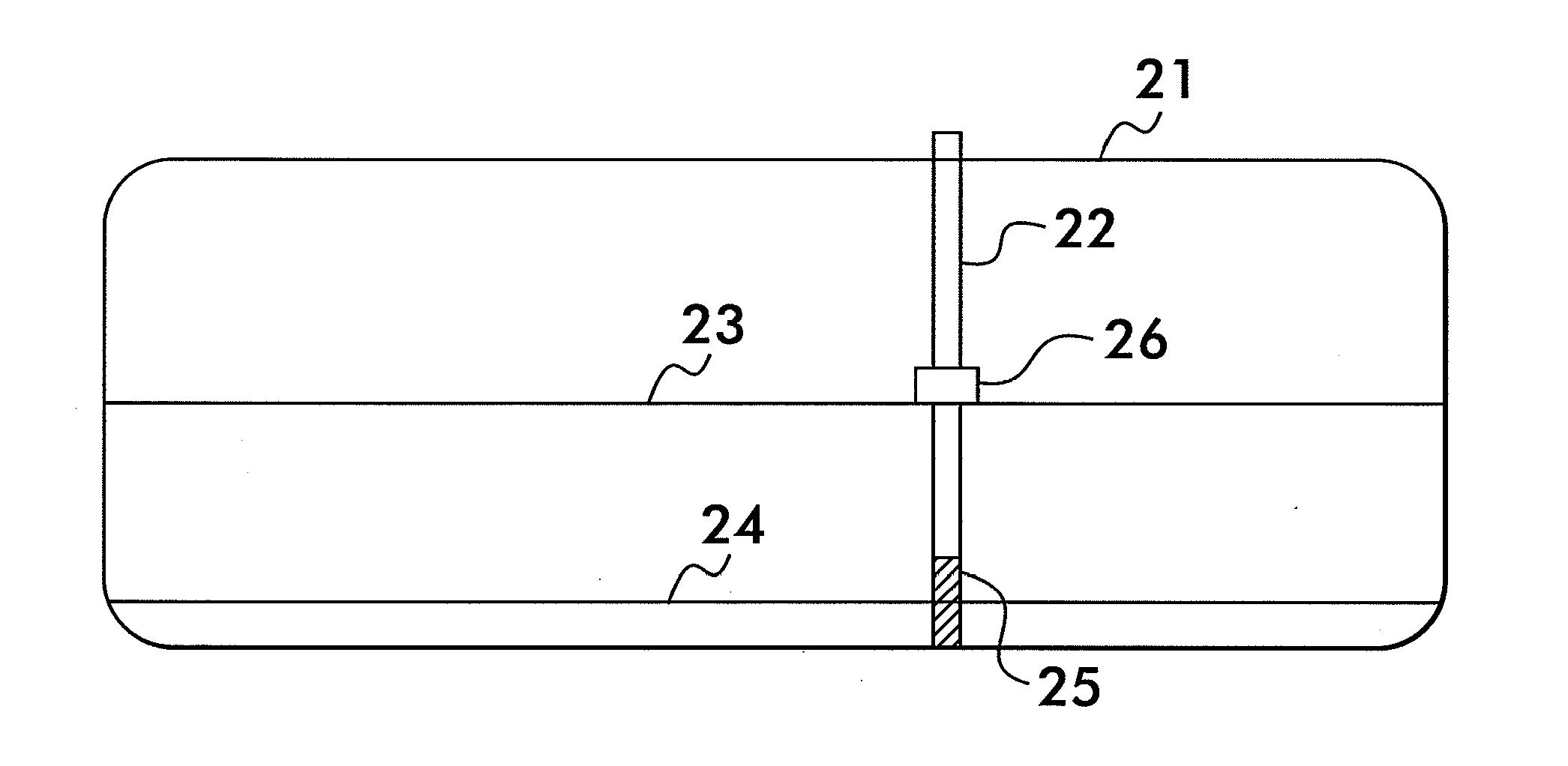
[0062]In FIG. 1, a magnetostrictive-probe-based Automated Tank Gauge or ATG (22) is deployed in storage tank (21) which contains a liquid product up to a certain level (23). The product float (26) floats on the product surface and provides an indication of product level to the ATG. An embodiment of the present invention is represented as a sensor (25) deployed at the bottom of the ATG probe. Wiring passing through the ATG powers this type of embodiment and allows for data from the sensor to be passed to the ATG control panel.

[0063]If the liquid stored in the tank is a ethanol-blended fuel, and if water is present such that phase separation has occurred, a level of aqueous ethanol (24) will form at the bottom of the tank. If such an aqueous ethanol layer covers the active region of sensor (25) then the sensor will detect the aqueous ethanol and report the problem to the control panel.

[0064]Even in cases where phase separation is not present, the sensor (25) can monitor the contents o...


PUM


Abstract

A fluid characterization sensor comprising a plurality of sensor segments is disclosed. Each segment comprises two electrodes, spaced apart so the fluid in the corresponding interval of depth for that segment is positioned between them. Complex current or impedance is measured by exciting one electrode with an AC signal, and measuring the amplitude and phase of the current in the other electrode. After automatically measuring and accounting for pre-determined gain, offset, temperature, and other parasitic influences on the raw sensor signal, the complex electrical impedance of the fluid between the electrodes is calculated from the measured phase/amplitude and/or real/imaginary components of the received electrical current signal and/or the variation of the measured response with variation in excitation frequency. Comparison of measured results with results taken using known fluids identifies fluid properties. Alternatively, measured results are compared to predicted results using forward models describing expected results for different fluids or contaminants.

Description

CROSS-REFERENCE TO RELATED APPLICATIONS[0001]This PCT application claims the benefit under 35 U.S.C. §119(e) of Provisional Application Ser. No. 61 / 010,397, filed on Jan. 9, 2008, entitled AUTOMATED PHASE SEPARATION AND FUEL QUALITY SENSOR; and Provisional Application Ser. No. 61 / 196,682, filed on, Oct. 21, 2008 entitled, SYSTEM FOR FUEL QUALITY DETECTION AND NOTIFICATION; the entire disclosures of which are incorporated by reference herein.FIELD OF THE INVENTION[0002]The disclosure relates to the fields of liquid level detection and fluid property measurement, and in particular level detection, leak detection, and fuel quality measurement of mixed fluids, including ethanol, gasoline, and water.BACKGROUND OF THE INVENTION[0003]Liquid fuel for retail and commercial use is often stored in above-ground storage tanks (AST's) and underground storage tanks (UST's). These tanks supply dispensers from which the fuel is pumped into vehicles or other storage tanks. Over the years, instrumenta...

Claims


Application Information

Patent Timeline
IPC IPC(8): G01R27/08
CPCG01F23/243G01F23/263G01F23/266G01N33/22G01M3/00G01N33/18G01M3/3245G01F22/00
Inventor DRACK, EARLE DAVID
Owner DIRACTION
Why Eureka
Try Eureka