
Wireless ultrasound transducer using ultrawideband

Inactive Publication Date: 2010-11-25
WORCESTER POLYTECHNIC INSTITUTE
View PDF14 Cites 56 Cited by
  • Summary
  • Abstract
  • Description
  • Claims
  • Application Information

AI Technical Summary

Benefits of technology

[0008]It would be desirable to eliminate the use of cables connecting a combined transducer and front end with the back end of an ultrasound system. It would also be desirable to integrate the transducer of an ultrasound system with the front end in a single housing. It would also be desirable to use transducers having large numbers of elements in ultrasound systems without using cables to transmit data to a back end for processing.
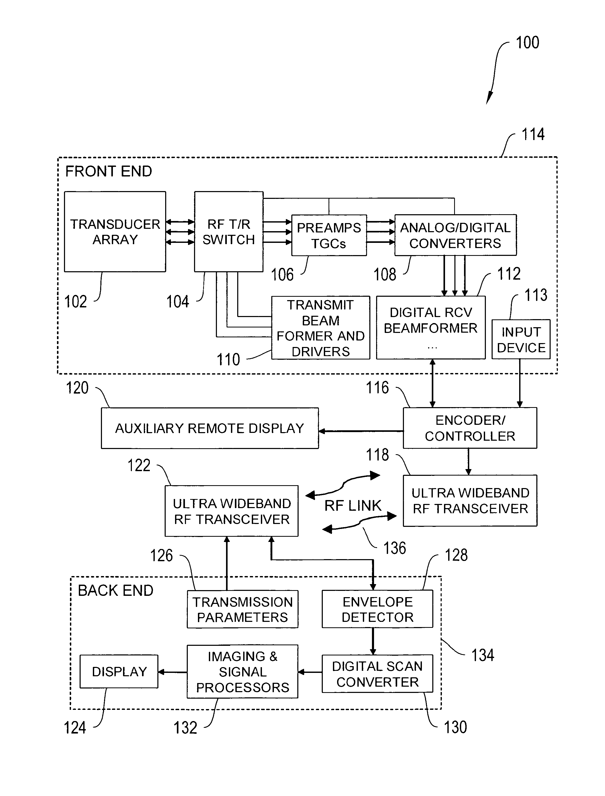
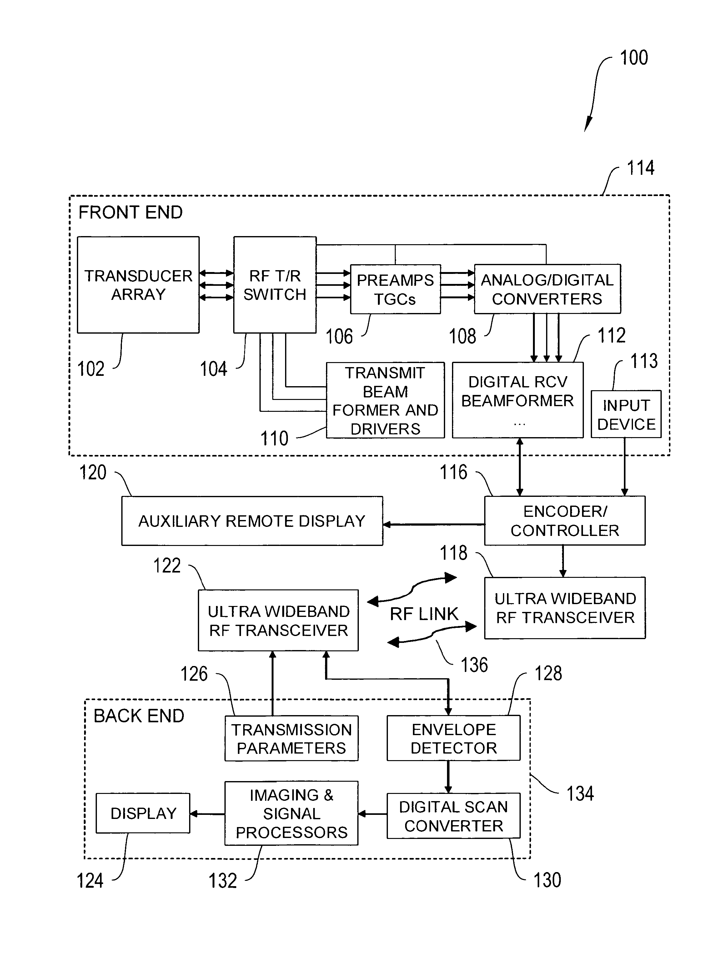
[0009]The present invention eliminates the need for such cables in ultrasound devices in which a front end is either directly integrated with a transducer array or placed in close proximity to the transducer array. Certain embodiments of invention utilize a UltraWideBand transceiver, to be denoted the front end UltraWideBand transceiver, which is connected to the beamformer output of the front end. The invention further utilizes a second UltraWideBand transceiver, to be denoted the back end UltraWideBand transceiver, which is connected to the back end. The two UltraWideBand transceivers communicate in half or full duplex mode using an UltraWideBand (UWB) wireless protocol, such that the back end UltraWideBand transceiver receives ultrasound data from the front end UltraWideBand transceiver via a peer-to-peer communication protocol, and the front end UltraWideBand transceiver receives control signals from the back end regarding beam forming in transmit and receive modes and other important imaging parameters via a peer-to-peer communication protocol.
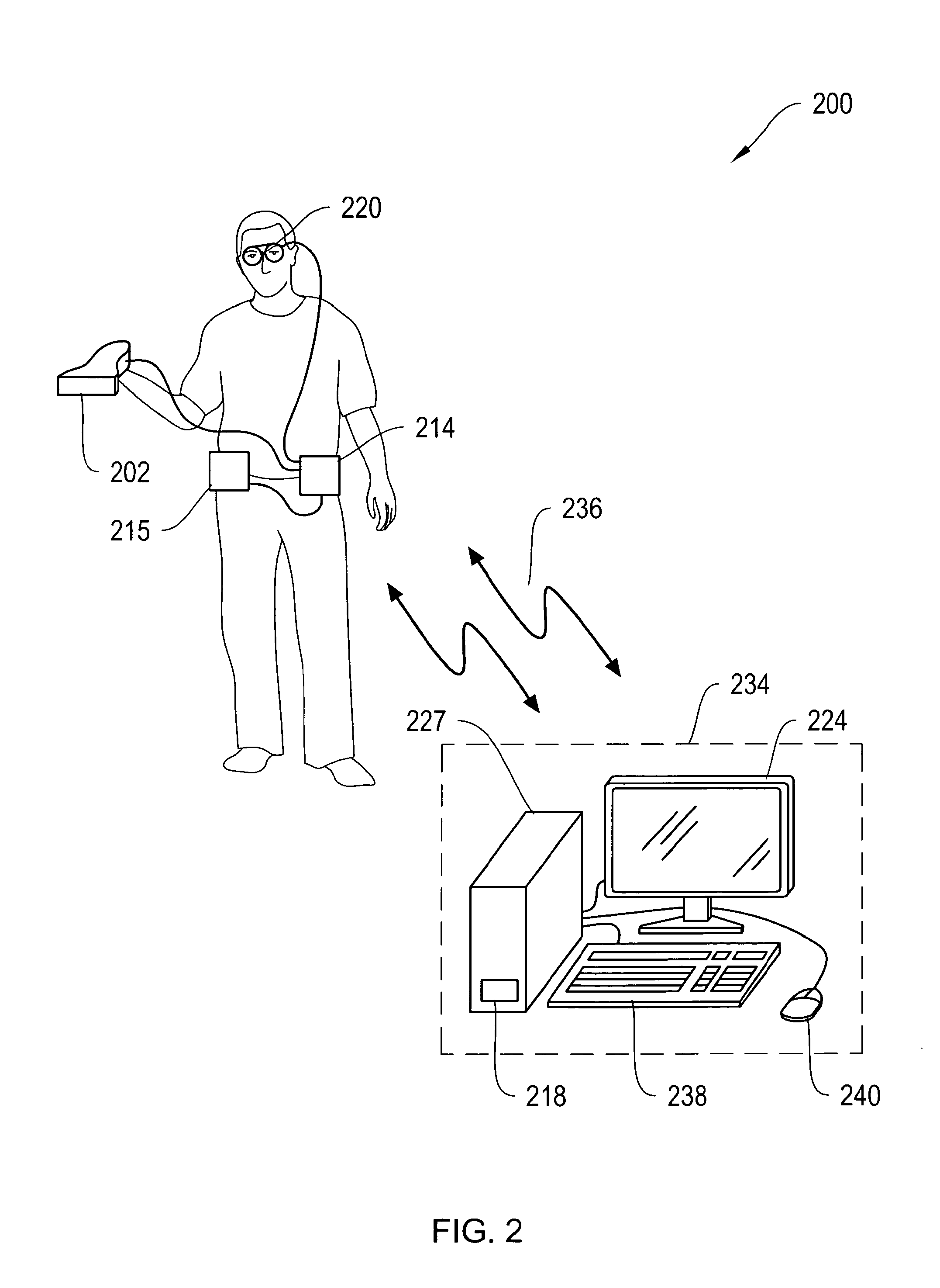
[0010]Because the transducer and front end can be integrated and miniaturized, the ultrasonographer (or operator) may obtain medical ultrasound images by operating the ultrasound transducer, and the RF data is transmitted to the back-end via the UWB-enabled RF-link. The present invention can be used in a wide variety of applications. For example, the UWB system can be used in a surgical suite, which can be advantageous because there can be fewer cables to interfere with the surgery and potentially contaminate the surgical suite. In one implementation, the UWB system is combined with a microphone and speech recognition system to replace the need for a keyboard, thereby eliminating an additional source of contamination and freeing up additional space. Alternatively, the UltraWideBand system may be combined with a touch screen display to replace the need for a keyboard. The present invention can also be advantageous because the system's weight can be reduced, thereby increasing ease of mobility. Furthermore, the present invention can allow a wider range of displays to be used (e.g., wearable displays and displays affixed to a patient's bed). Also, the present invention can allow computational capabilities to be expanded more easily, and can simplify networking of multiple ultrasound systems.
[0019]An ultrasound system of the present invention can, in some embodiments, further include a second front end, wherein the second front end can contain a second beamformer and a second front end UltraWideBand transceiver, wherein the second front end can be coupled to a second transducer array, and the second front end transmits ultrasound data processed by the second beamformer to a second back end UltraWideBand transceiver, wherein the second front end UltraWideBand transceiver is in communication with the back end, using the second front end UltraWideBand transceiver. In some embodiments, the back end can be in communication with a computer network via a satellite communication system. In some embodiments, the back end can be integrated into the infrastructure of a mobile vehicle. Such embodiments enable improved telemedicine and emergency response by allowing for on-site ultrasound where it was not previously available.

Problems solved by technology

A drawback to conventional ultrasound systems is the fact that the transducer's range of motion is limited to the length of the coaxial cable connecting it to the front end.
Using ultrasound systems with components connected by cables can limit or reduce the type, range, and / or safety of available clinical applications.
These cables can be hazardous in the surgery area, because space is at a premium, because they can be a source of contamination, and because they can be a hazard to medical personnel (e.g., can cause them to trip on the wires).
Cables can also limit accessibility and freedom of movement to restricted, compartmentalized, hazardous or contaminated areas in which diagnostic ultrasound is needed.

Method used


Image

  • Wireless ultrasound transducer using ultrawideband
  • Wireless ultrasound transducer using ultrawideband
  • Wireless ultrasound transducer using ultrawideband

Examples


Embodiment Construction

[0036]To provide an overall understanding of the invention, certain illustrative embodiments will now be described, including systems and methods for ultrasound imaging. However, it will be understood by one of ordinary skill in the art that the systems and methods described herein may be adapted and modified as is appropriate for the application being addressed and that the systems and methods described herein may be employed in other suitable applications, and that such other additions and modifications will not depart from the scope hereof.

[0037]FIG. 1 is a schematic diagram of ultrasound imaging system 100 that operates in accordance with an illustrative embodiment of the invention. The system includes front end 114, a transducer array 102, an input device 113, encoder / controller 116, front end UltraWideBand transceiver 118, which can transfer information to back end UltraWideBand transceiver 122 using a peer-to-peer communication protocol, and back end 134.

[0038]UltraWideBand (...


PUM


Abstract

Ultrasound imaging systems and methods are described that include a cableless front end having a UltraWideBand transceiver and a beamformer that transmit ultrasound data to a back end physically separated from the front end, with the back end having a UltraWideBand transceiver for receiving ultrasound data from the front end UltraWideBand transceiver via a peer-to-peer communication protocol. The back end unit can also receive and transmit commands to and from the front end unit to select an image mode and has a signal processor and scan converter that can convert ultrasound data into image data for display. An input device in the front end allows the operator to selectively display ultrasound data or patient data on an auxiliary worn display or the nearest local display.

Description

CROSS-REFERENCE RELATED APPLICATION[0001]This application claims the benefit of U.S. Provisional Application Ser. No. 60 / 898,343, titled “Untethered Ultrawideband Ultrasound Imaging, Information Management and Display,” filed Jan. 29, 2007, the entire contents of which are incorporated herein by reference.GOVERNMENT CONTRACT[0002]The U.S. Government has a paid-up license in this invention and the right in limited circumstances to require the patent owner to license others on reasonable terms as provided for by the terms of U.S. Army Medical Research Activity (USAMRAA) Contract No. DAMD17-03-2-0006.FIELD OF THE INVENTION[0003]In general, the invention relates to the field of ultrasound imaging for medical and non-destructive testing purposes, particularly ultrasound imaging using UltraWideBand (UWB) technology.BACKGROUND OF THE INVENTION[0004]Medical ultrasonography generally utilizes ultrasound technology to image soft tissues of the human body. Common applications in medicine inclu...

Claims


Application Information

Patent Timeline
IPC IPC(8): A61B8/14G06F19/00
CPCA61B8/00A61B8/4472A61B8/461A61B8/56A61B8/565G06F19/3418G01S7/003G01S7/52079G01S7/5208G01S15/899A61B8/585A61B8/4218G16H30/40G16H40/67
Inventor PEDERSEN, PEDER C.SZABO, THOMAS L.CORDEIRO, PHILIP JOSEPH
Owner WORCESTER POLYTECHNIC INSTITUTE
Learn More