MINIATURE PHASE-CORRECTED ANTENNAS FOR HIGH RESOLUTION FOCAL PLANE THz IMAGING ARRAYS

a thz imaging array and phase correction technology, applied in the direction of photometry using electric radiation detectors, optical radiation measurement, instruments, etc., can solve the problems of significant bottlenecks in long image acquisition time associated with such a raster scan, and significant reduction of the coupling efficiency of pixels positioned away from the lens axis

Inactive Publication Date: 2010-12-02
THE OHIO STATES UNIV
View PDF15 Cites 15 Cited by
  • Summary
  • Abstract
  • Description
  • Claims
  • Application Information

AI Technical Summary

Problems solved by technology

However, long image acquisition times associated with such a raster scan constitute a major bottleneck.
Although these detectors are attractive in conjunction with the double slot antennas (because of their high Gaussian beam coupling efficiency and diffraction limited patterns [3]), the need for local oscillator signal and relatively large low-pass IF filter sections do not allow for tightly packed array development.(2) Large number of antenna/detector elements (or equival

Method used


Image

  • MINIATURE PHASE-CORRECTED ANTENNAS FOR HIGH RESOLUTION FOCAL PLANE THz IMAGING ARRAYS
  • MINIATURE PHASE-CORRECTED ANTENNAS FOR HIGH RESOLUTION FOCAL PLANE THz IMAGING ARRAYS
  • MINIATURE PHASE-CORRECTED ANTENNAS FOR HIGH RESOLUTION FOCAL PLANE THz IMAGING ARRAYS

Examples


Embodiment Construction

THz Imaging System Overview

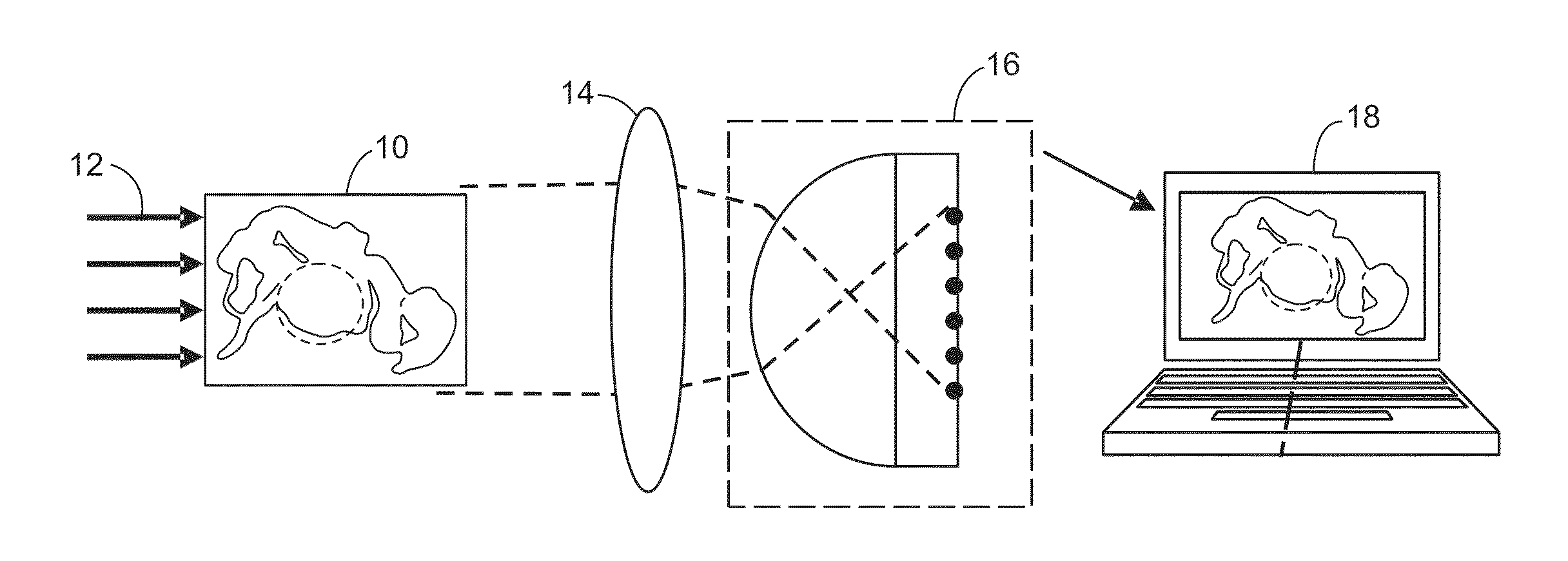
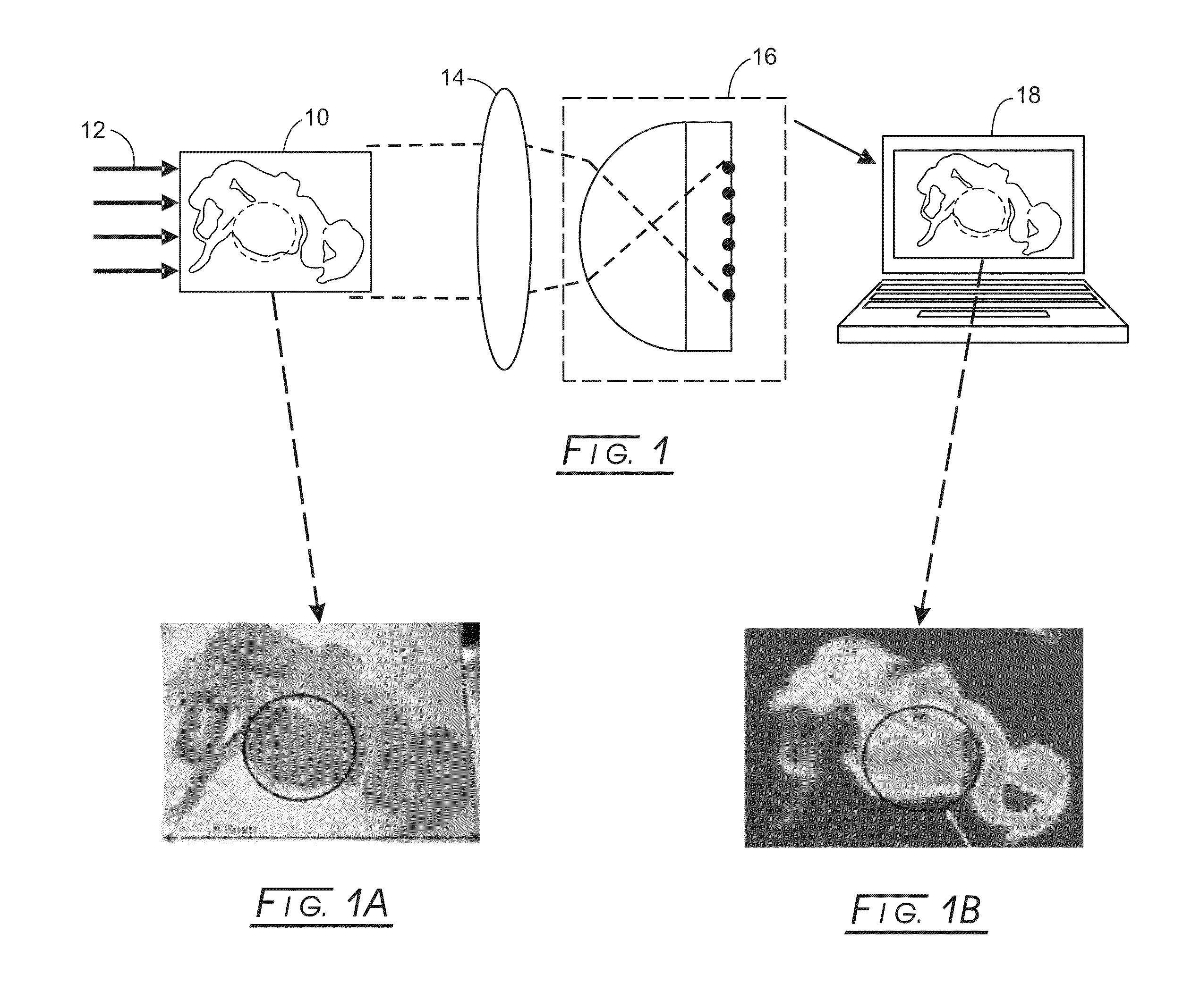
[0055]FIG. 1 demonstrates an overview of the disclosed THz imaging system. The object (e.g., tissue sample), 10, that is to be imaged is illuminated with uniform THz radiation, 12. The transmitted waves that have amplitudes modified according to the absorption properties of the object are guided to the imaging array through a lens system,14. The array elements are attached to the back of an extended hemispherical lens, 16, for detection from different angles of incidence. The lens is made from high resistivity silicon and its shape provides high gain and Gaussian beam coupling efficiency. Each focal plane array detector consists of a slot antenna structure (e.g., double slot) and Sb-heterostructure diode printed on it. The radiation received through the antenna is rectified on the diode, which acts as a half wave rectifier. The output of the rectification is DC voltage and higher frequency harmonics. The power level of the DC component corresponds to the m...


PUM


Abstract

An array of backward diodes of a cathode layer adjacent to a first side of a non-uniform doping profile and an Antimonide-based tunnel barrier layer adjacent to a second side of the spacer layer have a monolithically integrated antenna bonded to each backward diode. The Antimonide-based tunnel barrier may be doped with, for example, a non-uniform delta doping profile. An imaging/detection device includes a 2D focal plane array of an array of backward diodes, wherein each backward diode is monolithically bonded to an antenna, which array is located at the back of an extended hemispherical lens, and wherein certain of the arrays are tilted for correcting optics aberrations. The antennas may be a bow-tie antenna, a planar log-periodic antenna, a double-slot with microstrip feed antenna, a spiral antenna, a helical antenna, a ring antenna, a dielectric rod antenna, or a double slot antenna with co-planar waveguide feed antenna.

Description

CROSS-REFERENCE TO RELATED APPLICATIONS[0001]This application claims benefit of provisional application Ser. No. 61 / 181,809 filed on May 28, 2009 and entitled “Miniature Phase-Corrected Antennas for High Resolution Focal Plane THz Imaging Arrays”, the disclosure of which is expressly incorporated herein by reference.STATEMENT REGARDING FEDERALLY SPONSORED RESEARCH[0002]Not applicable.BACKGROUND[0003]Non-ionizing and penetrative nature of terahertz (THz) radiation makes it promising for various detection methods in the commercial and defense industry [1-2]. Likewise, in the medical scene, particular bands in the THz frequency regime can be identified as markers of malignant tissues. Tuned to these marker frequencies, THz radiation recently has been proposed as an effective tool for cancer detection that will exhibit satisfactory resolution, substantial penetration depth, and non-harmful radiation properties in contrast to the x-ray technology. This is especially true and important fo...

Claims


Application Information

Patent Timeline
IPC IPC(8): G01J5/20H01Q1/00
CPCG01J1/4228G01J5/0837H01Q3/40H01L27/14625H01Q25/007H01L27/14605H01Q19/062
Inventor SERTEL, KUBILAYMOSBACKER, H. LEEMUMCU, GOKHANSMITH, PHILLIP
Owner THE OHIO STATES UNIV
Why Eureka
Try Eureka