

Electronic device and method for dc-dc conversion with variable bias current
a technology of dc-dc converter and bias current control, which is applied in the direction of electric variable regulation, process and machine control, instruments, etc., can solve the problems of increased cost, increased circuit complexity, and increased susceptibility to false triggers
- Summary
- Abstract
- Description
- Claims
- Application Information
AI Technical Summary
Benefits of technology
Problems solved by technology
Method used
Image

Examples
Embodiment Construction
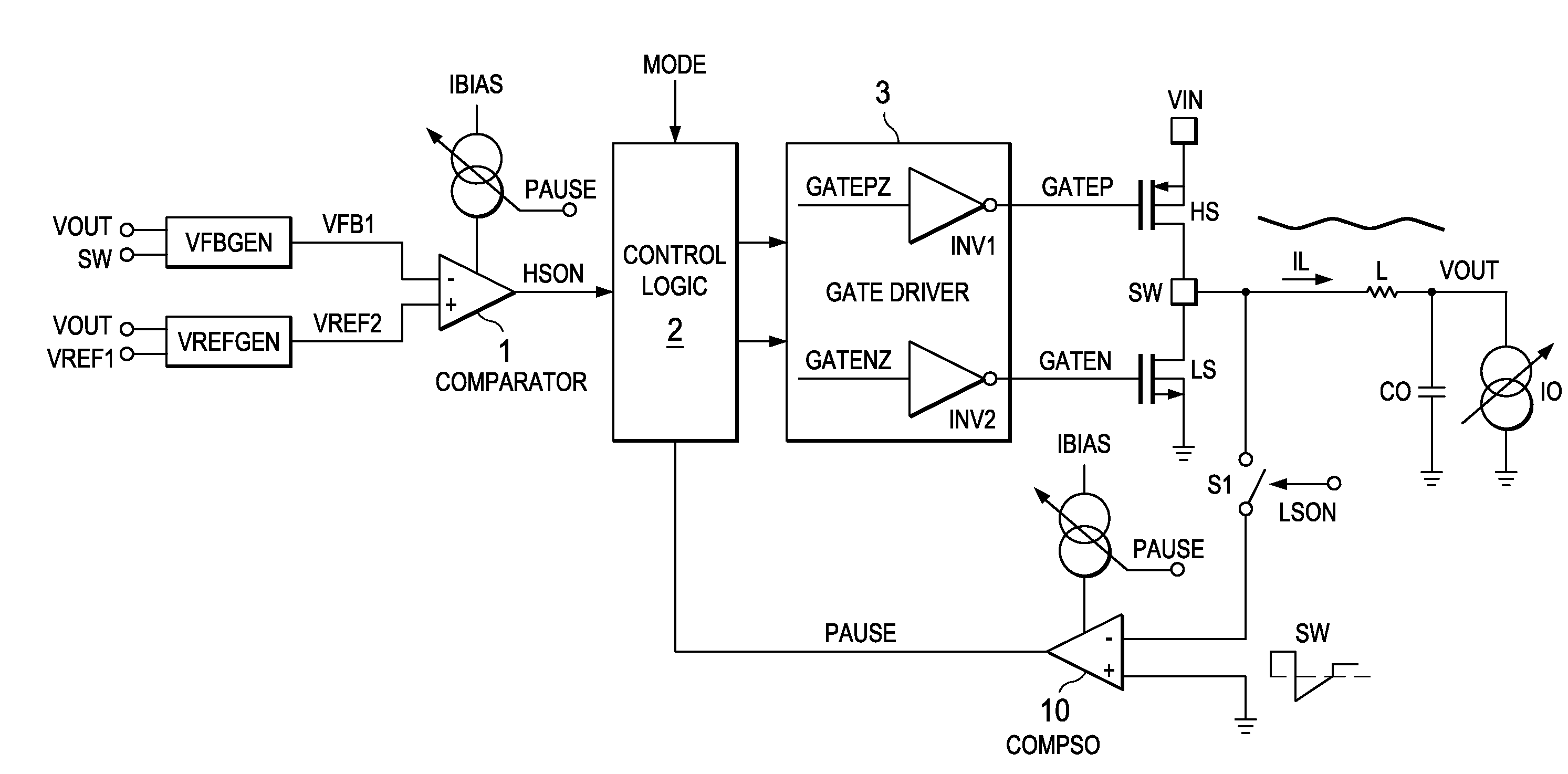
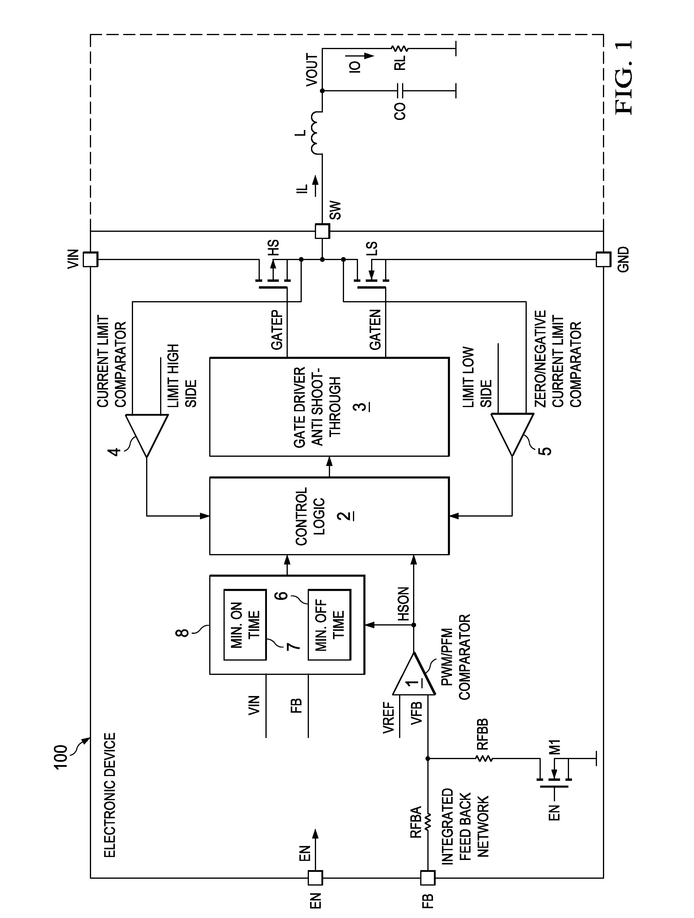
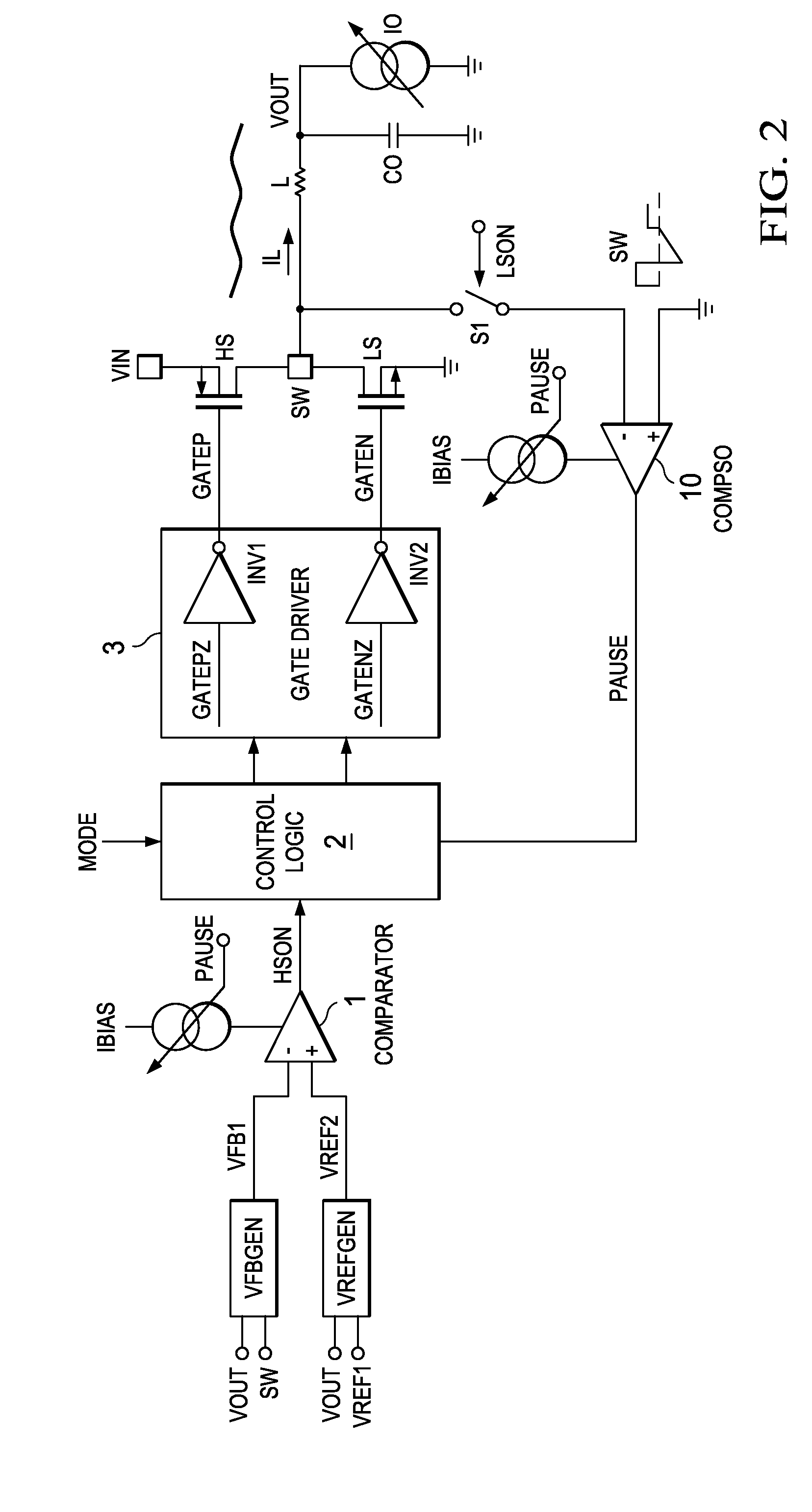
[0016]FIG. 1 shows a simplified circuit and block diagram of an electronic device 100 to which the aspects of the invention apply. The electronic device can comprise or substantially be an integrated circuit. The electronic device can be configured to perform DC-DC conversion. The solid line suggests how integrated and external components can be arranged. However, other configurations are also possible. This embodiment relates to a DC-DC converter with two power switches HS and LS. Switch HS is referred to as high side switch and implemented with a PMOS transistor. The other switch LS is referred as the low side switch and implemented with an NMOS transistor. The high side switch HS is coupled with one side of its channel to receive the primary input voltage VIN. The low side switch LS is coupled with one side of its channel to the other side of the channel of the high side switch HS. This node is the switching node SW. The other side of the channel of the low side switch is coupled...
PUM
 Abstract
Description
Claims
Application Information