System and method for monitoring hemodynamic state

a hemodynamic state and system technology, applied in the field of system and method for monitoring the hemodynamic state, can solve the problems of inability to accurately measure the pulse transit time and thus blood pressure, pain in each inflation, and patient risk,

Inactive Publication Date: 2010-12-09
GENERAL ELECTRIC CO
View PDF13 Cites 87 Cited by
  • Summary
  • Abstract
  • Description
  • Claims
  • Application Information

AI Technical Summary

Problems solved by technology

Automatic blood pressure cuffs can be used for this application, by inflating them as rapidly as is possible; however, this provides blood pressure data only at 1 to 2 minute intervals, and each inflation can be painful, especially for elderly or hypertensive patients.
However, these techniques involve making an incision through the patient's skin and inserting the catheter into a blood vessel.
As a consequence, this invasive procedure entails some risk of complications for the patient.
The inability of prior pulse transit time-based monitors to account for the cardiac pre-injection period results in an inaccurate measurement of the pulse transit time and thus blood pressure.
Additionally, changes in the compliance of the blood vessels also affect the pulse transit time estimates.
Previous monitoring systems have been unable to separate changes due to compliance from changes due to blood pressure.
As a consequence, some degree of inaccuracy has existed in calculating blood pressure from the variation of the pulse transit time.
Similar to PTT, these techniques lack the ability to adapt to acute physiological changes affecting the biomechanical model, such as changes in the arterial compliance.
Since plythesmogrpaphy measures the change in the total volume, contributions from the arterial and venous systems cannot be separated contributing to errors in the arterial blood pressure measurement.

Method used


Image

  • System and method for monitoring hemodynamic state
  • System and method for monitoring hemodynamic state
  • System and method for monitoring hemodynamic state

Examples


examples

[0042]The examples that follow are merely illustrative, and should not be construed to be any sort of limitation on the scope of the claimed invention.

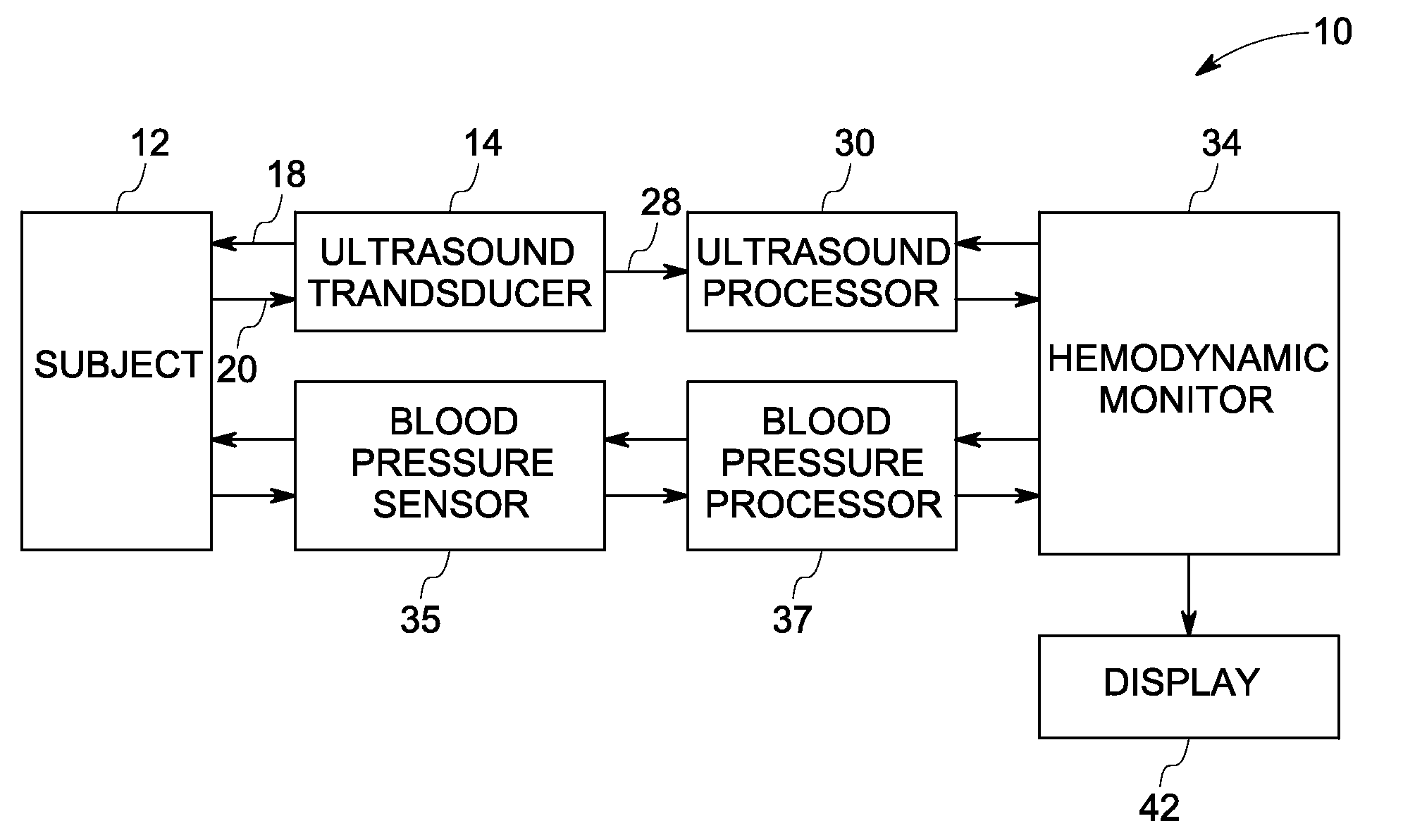
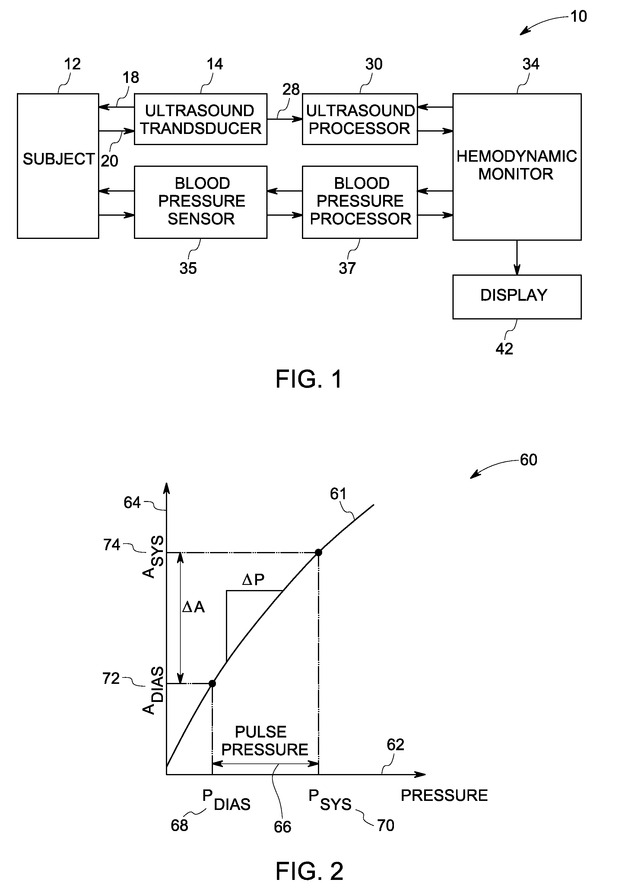
[0043]An animal experiment was conducted to evaluate the feasibility of the proposed approach for compliance-based blood pressure estimation. A pig was used as a large animal model for the cardiovascular system. The animal was anesthetized and instrumented with an invasive pressure catheter placed in the femoral artery with the location verified using ultrasound. Ultrasound data were acquired with a high frequency vascular ultrasound probe on a cardiovascular ultrasound scanner. The arterial blood pressure was continuously monitored invasively using a pressure sensor mounted on a catheter inserted in the animal's femoral artery. A data acquisition system was used to collect invasive pressure readings at a sample rate of 400 Hz during the entire experiment. Ultrasound B-mode and color flow data were acquired on the femoral artery oppos...


PUM


Abstract

A method for continuous non-invasive hemodynamic state monitoring in a subject is provided. The method includes acquiring continuous ultrasound data via an ultrasound transducer attached to the subject. The method also includes estimating continuous arterial waveforms based upon the acquired ultrasound data. The method further includes deriving hemodynamic parameters for each cardiac cycle from the arterial waveforms. The method also includes defining a current hemodynamic state of the subject by setting limits on one or more hemodynamic parameters based upon the variation of these parameters over an initial period of time. The method further includes continuously monitoring a hemodynamic state of the subject. The method further includes comparing a current state for one or more hemodynamic parameters of the subject to previously determined limits for the one or more hemodynamic parameters, and either outputting a trigger signal or alarm to a hemodynamic state monitor in an event that a change is detected in the current state of the one or more hemodynamic parameters or converting the arterial parameters into a continuous estimate of the arterial blood pressure in an event that a change is not detected.

Description

BACKGROUND[0001]The present invention relates generally to methods and apparatus for continuous, non-invasive monitoring of the hemodynamic state and the arterial blood pressure of a subject.[0002]A method for the determination of non-invasive beat-by-beat (continuous) systolic and diastolic arterial blood pressures has long been desired in patient monitoring. Automatic blood pressure cuffs can be used for this application, by inflating them as rapidly as is possible; however, this provides blood pressure data only at 1 to 2 minute intervals, and each inflation can be painful, especially for elderly or hypertensive patients.[0003]A common technique for continuously measuring blood pressure is to insert a saline-filled catheter through the patient's vascular system to the point at which it is desired to perform the measurements. The catheter is connected to a pressure sensor, which measures the pressure in the vessel. An alternative method uses a catheter with a pressure sensor at th...

Claims


Application Information

Patent Timeline
Patent Type & Authority Applications(United States)
IPC IPC(8): A61B8/00
CPCA61B5/02116A61B5/024A61B5/0816A61B5/145A61B8/04
Inventor DENTINGER, AARON MARK
Owner GENERAL ELECTRIC CO
Why Eureka
Try Eureka