

Spallation-resistant multilayer thermal spray metal coatings
a technology of thermal spray coating and metal coating, applied in coatings, chemical instruments and processes, transportation and packaging, etc., can solve the problems of presenting health risks to workers in the chrome plating process, cracking and spalling of materials,
- Summary
- Abstract
- Description
- Claims
- Application Information
AI Technical Summary
Problems solved by technology
Method used
Image

Examples
example 1
[0033]A multilayer coating of WC—Co bond coating layer, a Co—Cr—Mo—C support coating layer, and a WC—Co based surface coating layer were applied to an Almen Type N steel strip of 0.75 mm thick prepared according to SAE J442 having hardness of HRC 45-50. Each of the coating layers was applied by Jet Kote, a commercially available high velocity oxyfuel thermal spray process. The fuel used was hydrogen and the parameters as shown here in Table A:
TABLE ANozzle,Part speed,TorchAlloyH2 SCFHO2 SCFHAr SCFHPowder, g / minBore × lengthSD, inchesft / minspeed, in / secJK11711505705735.5¼× 982940.8Stellite 2112005506340.0¼× 982940.8JK120H13806005737.0¼× 683591.0
[0034]The bond coating layer was 25 microns thick of a composite carbide material (JK® 117) of 83 wt % WC in a matrix of 17 wt % Co. The support coating layer was 225 microns thick and formed from a fully pre-alloyed powder (JK 571, corresponding generally to Stellite 21) of approximately 28 wt % Cr, 5 wt % Mo, 2.5 wt % Ni, 0.25 wt % C, and ba...
example 2
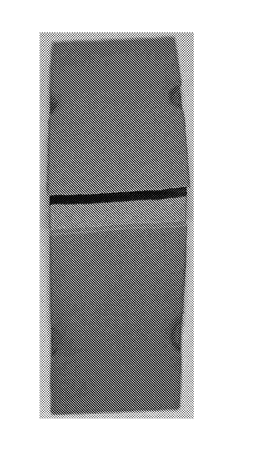
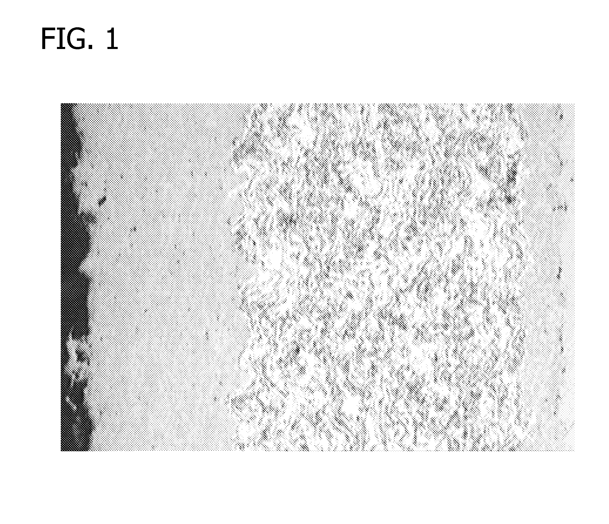
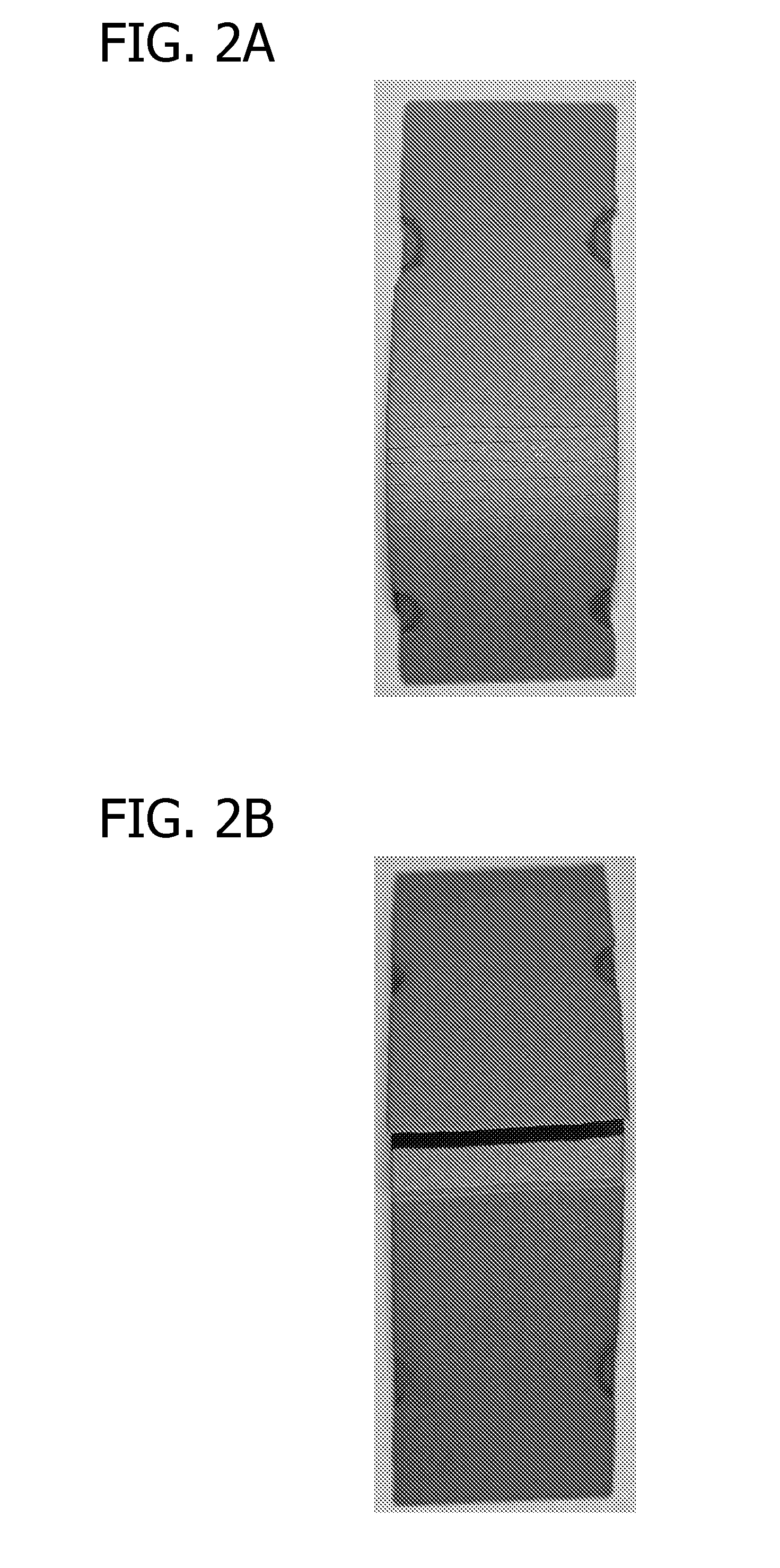
[0035]A monolayer of alloy JK® 120H having a thickness of 375 microns was applied to a hardened high strength steel coupon (an Almen Type N steel strip of 0.75 mm thick prepared according to SAE J442 having hardness of HRC 45-50). JK® 120H is a cemented carbide material comprising 86 wt % WC in a matrix of 10 wt % Co and 4 wt % Cr. This coupon and the coupon of Example 1, each having dimensions of 0.76 mm by 19 mm by 76 mm, were subjected to a 180-degree bending test. The coupon of Example 1 is shown in FIG. 2A and the coupon of Example 2 is shown in FIG. 2B. FIG. 2A shows only barely visible fine cracks in the apex region, while FIG. 2B shows a brittle fracture and spalling at the apex.
example 3
[0036]A fatigue test according to ASTM E-466-96 was performed. Small straight gage fatigue bars of AISI 4340HT with a diameter of 0.25 inch were coated in the 0.75-inch gage length and ground to a finish of Ra 32. The stress level applied was 220 ksi at R=−1, which means the compressive load is equal to tensile load. The frequency was 20 Hz. The maximum stress was set at the yield point of the base metal to simulate severe conditions. The results are presented in Table 1. Specimens 107, 108, 109, and 110 correspond to the three-layer coatings of the invention prepared under the process as described in Example 1, but with the layer thicknesses described below. Specimens 103, 104, 105, and 106 correspond to two-layer coatings not of the invention with the layers applied by the Jet Kote thermal spray process. The fuel in all the foregoing spray operations was hydrogen.
TABLE 1SMALL BAR ASTM E466 FATIGUE TESTCycles25-micron thickThicknessThicknesstoSpecimen1st Layer2nd Layerin Microns3rd...
PUM
| Property | Measurement | Unit |
|---|---|---|
| thickness | aaaaa | aaaaa |
| thickness | aaaaa | aaaaa |
| thickness | aaaaa | aaaaa |
Abstract
Description
Claims
Application Information