Multiband transceiver and positioning system using the transceiver

a transceiver and multi-band technology, applied in direction finders, instruments, measurement devices, etc., can solve the problems of high equipment cost due to the use of atomic clocks, large power consumption in high-aware positioning and positioning without the aid of base stations, and difficulty in underground us

Active Publication Date: 2010-12-23
NEC CORP
View PDF1 Cites 43 Cited by
  • Summary
  • Abstract
  • Description
  • Claims
  • Application Information

AI Technical Summary

Benefits of technology

[0062]As so far described, according to the present invention, it is possible to perform distance measurement by means of radio waves...

Problems solved by technology

Problems with a positioning system utilizing an atomic clock, such as GPS, include: high equipment cost due to the usage of an atomic clock: difficulty in underground usage because of the necessity of synchronization with the atomic clock on the satellite; large power consumption in high accuracy positioning and positioning without the aid of base stations; and others.
A problem of this technique is that since positioning accuracy becomes approximately the same as that of the base station installation spacing between the positioning equipment, many pieces of positioning equipment need to be provided thereby leading to high deployment cost.
A problem with a positioning system utilizing a wide bandwidth is that a larger bandwidth generally results in larger reception power, and that since the accuracy is determined by the inverse of the bandwidth, use of wireless LAN does not provide enough bandwidth thereby resulting in poor accuracy.
Although impulse-UWB, whereby a high accuracy can be expected, can suppress transmission power to a very low level, it requires larger reception power and th...

Method used


Image

  • Multiband transceiver and positioning system using the transceiver
  • Multiband transceiver and positioning system using the transceiver
  • Multiband transceiver and positioning system using the transceiver

Examples


first exemplary embodiment

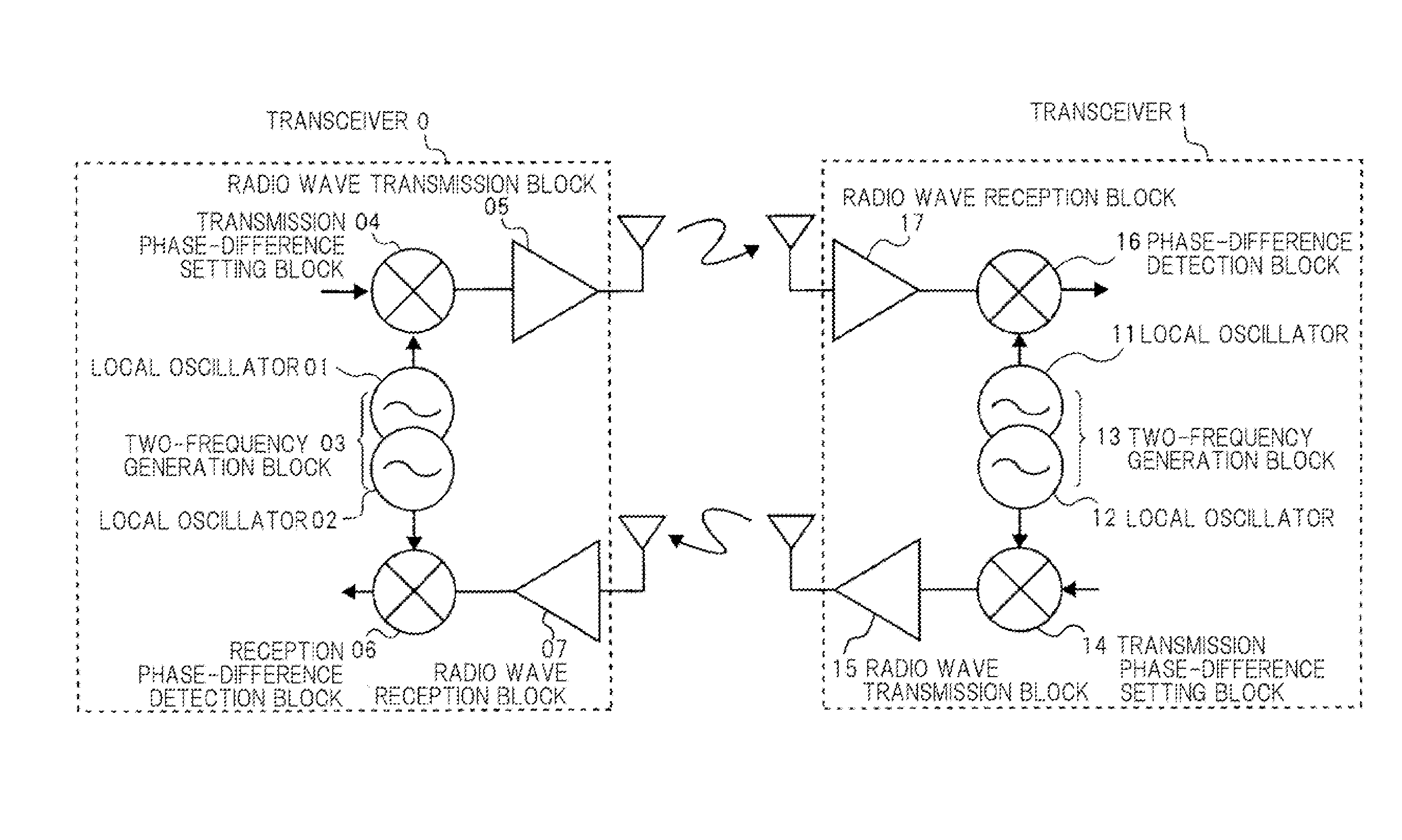
[0089]FIG. 5 shows a first exemplary embodiment.

[0090]Two transceivers (TRX)0 and (TRX)1 respectively include radio wave transmission block 05, 15, radio wave reception block 07, 17, transmission phase-difference setting block 04, 14, reception phase-difference detection block 06, 16, and two-frequency generation block 03, 13. Two-frequency generation block 03 is made up of local oscillators 01 and 12, and two-frequency generation block 13 is made up of local oscillators 11 and 12.

[0091]At two-frequency generation block 03 of transceiver TRX0, local oscillator 01 and local oscillator 02 generate two frequencies which are in a relationship of 1-to-m (m is a rational number), and at two-frequency generation block 13 of transceiver TRX1, local oscillator 11 and local oscillator 12 generate two frequencies which are in a relationship of 1-to-m (m is a rational number).

[0092]At transmission phase-difference setting block 04 of transceiver TRX0, a phase difference between local oscillator...

second exemplary embodiment

[0114]FIG. 7 shows a second exemplary embodiment.

[0115]Suppose that the distance between transceiver TRX0 and transceiver TRX1 is L01, the distance between transceiver TRX0 and transceiver TRX2 is L02, and the distance between transceiver TRX1 and transceiver TRX2 is L12.

[0116]When a signal of phase φf0 and frequency ff is transported from transceiver TRX0, transceiver TRX2 receives the signal of this frequency ff and obtains phase φf2 of baseband signal as a reception result. At the same time, when a signal of phase φr1 and frequency fr is transported from transceiver TRX0, transceiver TRX2 receives the signal of this frequency fr and obtains phase φr2 of baseband signal as a reception result. Here, frequencies fr and ff are in the relationship of fr=m×ff.

[0117]Suppose the phase difference between the local oscillator of frequency ff of transceiver TRX0 and the local oscillator of frequency fr of transceiver TRX1 is Δφ01, the phase difference between the local oscillator of frequen...

example 1

[0120]FIG. 9 illustrates a first example of the present invention.

[0121]FIG. 9 is a circuit diagram to show the configuration of an example of the multiband transceiver used in the present invention.

[0122]The present example is made up of phase-setting device 601, phase calculator 617, cosine signal generator 603, mixers 603, 604, 618 and 619, adder 605, high-frequency amplifiers 606 and 620, reference signal source 608, frequency dividers 609, 611 and 613, switches 610 and 621, phase shifters 612 and 614, micro processor (MPU) 615, bandpass filters 622 and 624, and antenna 623.

[0123]When the multiband transceiver shown in FIG. 9 acts as transceiver TRX0 in the first exemplary embodiment, a phase in accordance with the signal indicating the phase instructed by microprocessor (MPU) 615 is set at phase-setting device 601. Cosine signal generator 602 and sine signal generator 607 generate a cosine signal and a sine signal in accordance with phases set at phase-setting device 601 and ou...


PUM


Abstract

The present invention comprising: a first local oscillator for generating a first frequency; a second local oscillator for generating a second frequency; phase-difference setting means for setting a first phase difference between a transmission signal and an output of the aforementioned first local oscillator; phase-difference detection means for detecting a second phase difference which is the phase difference between a reception signal and an output of the aforementioned second local oscillator, and calculation means for calculating a distance to a communication counterpart from a third phase difference and a fourth phase difference which are notified by the communication counterpart, and from the aforementioned first phase difference and second phase difference, wherein the third phase difference is set to the second frequency by the communication counterpart, and the fourth phase difference is set to the first frequency by the communication counterpart.

Description

TECHNICAL FIELD[0001]The present invention relates to a multiband transceiver having a distance measurement function and a distance measurement system utilizing the transceiver.BACKGROUND ART[0002]So far, various positioning systems have been proposed. FIG. 1 shows a comparison of various kinds of positioning systems with the ordinate as positioning accuracy and the abscissa as the spacing between equipment required for positioning.[0003]Positioning systems typified by GPS (Global Positioning System) perform time synchronization by using an accurate clock such as an atomic clock and measure the difference in arrival times of radio waves to realize positioning. Problems with a positioning system utilizing an atomic clock, such as GPS, include: high equipment cost due to the usage of an atomic clock: difficulty in underground usage because of the necessity of synchronization with the atomic clock on the satellite; large power consumption in high accuracy positioning and positioning wi...

Claims


Application Information

Patent Timeline
IPC IPC(8): G01S13/84H04B1/38H04W64/00
CPCG01S13/84H04B1/005G01S13/87
Inventor AOKI, YUUICHI
Owner NEC CORP
Why Eureka
Try Eureka