Optical apparatus

a technology of optical equipment and optical cavity, applied in the field of optical apparatus, can solve the problems of low cavity finesse of the fibre feedback cavity, inability to continuously tunable, and not readily accessible to either of the conventional approaches

Active Publication Date: 2010-12-30
HERIOT WATT UNIV
View PDF6 Cites 20 Cited by
  • Summary
  • Abstract
  • Description
  • Claims
  • Application Information

AI Technical Summary

Benefits of technology

[0009]According to a first aspect of the present invention, there is provided an optical parametric oscillator (OPO) comprising:—a resonant cavity for signal light; and an optically non-linear medium disposed in the resonant cavity for converting pump light into the signal light, wherein the resonant cavity is arranged so that in operation signal

Problems solved by technology

For many applications there is an energy range (for example, 10-100 nJ) and repetition-rate (for example several MHz to several 10s of MHz) range that is desirable but which is not readily accessible to either of the conventional approaches.
However, the system described in T. Südmeyer et al requires a high average power c

Method used


Image

  • Optical apparatus
  • Optical apparatus
  • Optical apparatus

Examples


Embodiment Construction

[0091]Throughout the following description identical reference numerals will be used to identify like parts.

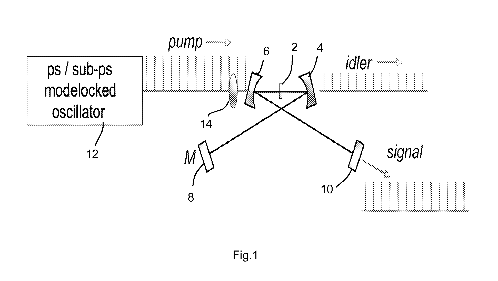
[0092]FIG. 1 is a schematic diagram of a known, synchronously pumped optical parametric oscillator (OPO). The OPO comprises a non-linear crystal 2 contained in a resonant optical cavity. The resonant optical cavity is defined by two focussing mirrors 4, 6, a further mirror (M) 8 and output coupler 10. The output coupler 10 is a partially reflective mirror. A picosecond or sub-picosecond mode-locked oscillator 12 is used as a pump source, and is aligned with a focussing lens arrangement 14.

[0093]In operation, pump pulses with a fixed repetition frequency (typically ˜100 MHz) are focused by the focussing lens arrangement into the nonlinear crystal 2 contained in the resonant optical cavity. Each pump pulse forms, with radiation at the signal frequency, a mode in the nonlinear crystal, which generates a signal pulse and an idler pulse. The resonant cavity is arranged so that the ...


PUM


Abstract

An optical parametric oscillator (OPO) comprises a resonant cavity for signal light, and an optically non-linear medium disposed in the resonant cavity for converting pump light into the signal light, wherein the resonant cavity is arranged so that in operation signal light is repeatedly output from and returned to the optically non-linear medium along a signal light path in a continuously repeating cycle, and the OPO comprises delay means for extending the time taken for signal light output from the optically non-linear medium in operation to return to the optically non-linear medium along the signal light path.

Description

[0001]This application claims the benefit of United Kingdom patent application No. GB090295.8, filed May 29, 2009 and U.S. Provisional Patent Application No. 61 / 226,414, filed Jul. 17, 2009, the entire disclosures of which are incorporated by reference herein.FIELD OF THE INVENTION[0002]The present invention relates to an optical apparatus and method, and in particular to an optical parametric oscillator and a method for operation of such optical parametric oscillator.BACKGROUND TO THE INVENTION[0003]Tunable near- to mid-infrared (IR) ultrafast optical pulses have a variety of applications in scientific, metrology and engineering contexts, including time-resolved spectroscopy, frequency-resolved spectroscopy, nonlinear spectroscopy, laser waveguide inscription, nonlinear microscopy and laser machining.[0004]Two sources of such pulses are known in the prior art: (a) low-energy synchronously-pumped optical parametric oscillators (OPOs), operating at energies of typically <5 nJ and ...

Claims


Application Information

Patent Timeline
IPC IPC(8): G02F1/39
CPCB67D1/0021B67D3/0012B67D1/0041G02F1/39G02F2201/20G02F2203/13G02F2203/54G02F1/3542
Inventor REID, DERRYCK TELFORDKORNASZEWSKI, LUKASZLAMOUR, TOBIAS PAUL
Owner HERIOT WATT UNIV
Why Eureka
Try Eureka