Methods and devices for delivering microwave energy

a microwave energy and antenna technology, applied in the field of microwave antennas, can solve the problems of non-uniform lesion profile along the length of the antenna, device shaft heating, and shape ablation, and achieve the effects of increasing metabolism, facilitating fat extraction, and increasing the efficacy of therapy

Active Publication Date: 2011-01-06
MICROCUBE
View PDF32 Cites 105 Cited by
  • Summary
  • Abstract
  • Description
  • Claims
  • Application Information

AI Technical Summary

Benefits of technology

[0008]Several medical applications of the invention for applying energy such as microwave energy to target materials such as tissue are disclosed herein. Energy may be applied to tissue to achieve a variety of clinically useful effects. Examples of such effects include, but are not limited to: 1. ablating tissue to kill or otherwise damage tissue, 2. causing heat-induced modification of tissue (e.g. heat shrinkage of collagen), 3. causing heat-induced modification of an artificially introduced material (e.g. heat induced polymerization of an injected monomer), 4. warming tissue to change the metabolic activity of tissue (e.g. warming tissue to increase the metabolism), 5. causing fat liquefaction e.g. to ease fat extraction during Microwave Assisted Lipoplasty, 6. causing controlled tissue death to debulk tissue for treating conditions such as Obstructive Sleep Apnea, BPH, etc., 7. delivering energy to tissue to change the electrophysiological characteristics of that tissue, and 8. increasing the efficacy of a therapy (e.g. chemotherapy) in a local region of tissue.

Problems solved by technology

Many of the existing antennas have common disadvantages such as device shaft heating and non-uniform lesion profile along the length of the antenna.
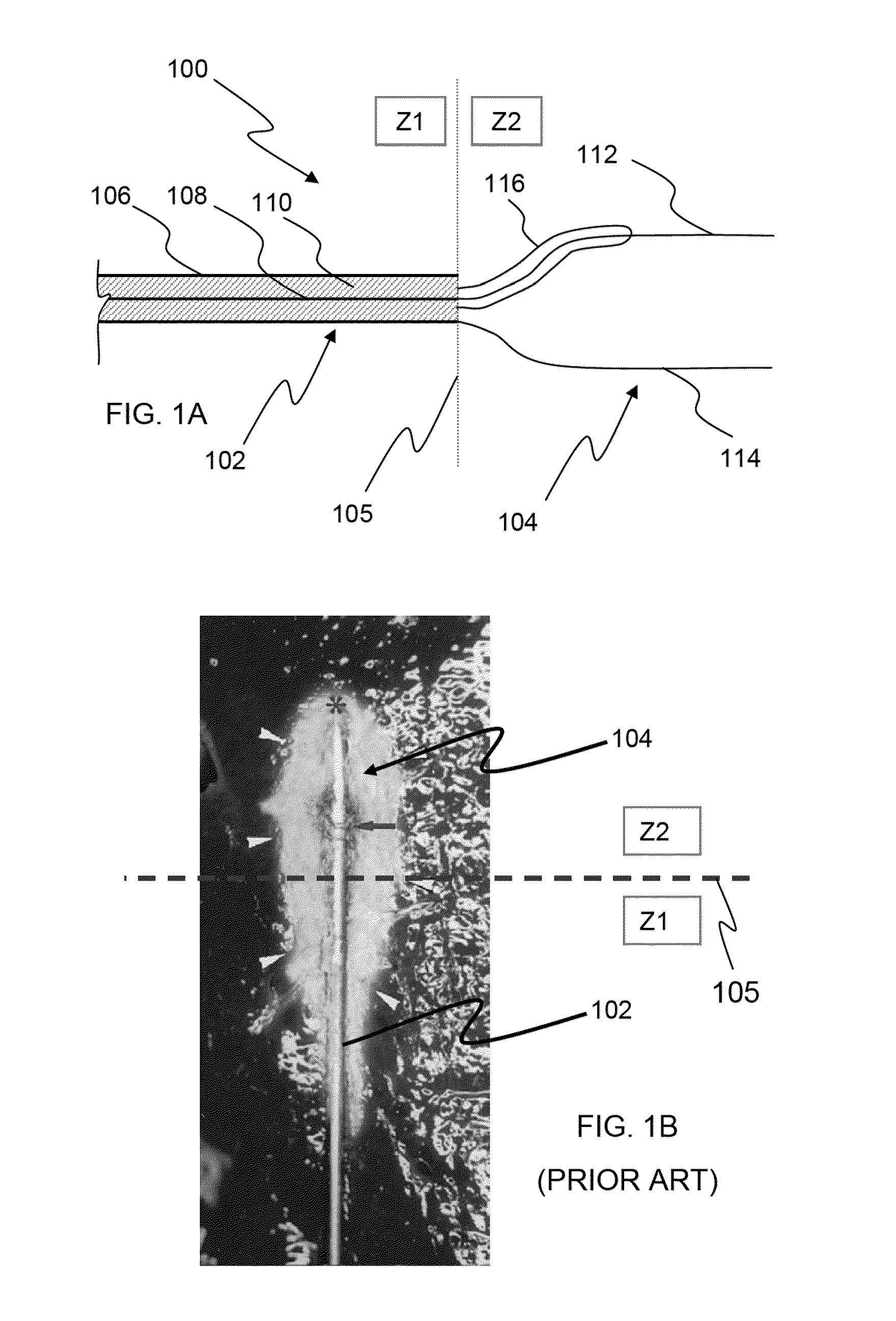
FIG. 1B illustrates some of the common disadvantages of prior art antennas used for ablating solid tissue such as solid tumors.
Such an ablation shape is caused due to the undesired backward coupling of the microwave field emitted by the antenna to the distal region of a conductor of the transmission line (e.g. the outer conductor of a coaxial cable).
This portion of the microwave field can damage healthy tissue and increase the morbidity of the medical procedure.
Further, this portion of the microwave field can heat up the transmission line and further damage healthy tissue.
However, this increases the outer diameter of the device thereby increasing the invasiveness of the procedure.
Further, devices with a cooling mechanism need extra equipment for circulating the coolant through the cooling mechanism thereby increasing the device complexity and cost.
A large portion of the field is located over non-target tissue and is thus wasted.
This reduces the efficiency of the antenna.
Higher power delivery requires the use of larger diameter transmission lines which in turn increases the invasiveness of the procedure.
However, such elements are located on the outer surface of the transmission line and thus increase the size of the transmission line.
This in turn increases the invasiveness of the procedure.
Also, it is difficult to use a single existing microwave antenna such as a single monopole antenna to ablate tumors that have a thickness or diameter of a few centimeters in a sufficiently short time.
For many cancer-related applications, the targeted tumors have an excessive size (e.g. diameter of several centimeters) and a single monopole antenna is of limited use.
This increases the complexity of the ablation system.
The overall size and cost of the ablation device is also increased due to more number of elements employed in the system.
Also, this increases the invasiveness and complexity of the procedure.
However, this may increase the temperature of the transmission line of the antenna to unsafe levels thereby increasing the risk of damaging healthy tissue.

Method used


Image

  • Methods and devices for delivering microwave energy
  • Methods and devices for delivering microwave energy
  • Methods and devices for delivering microwave energy

Examples


Embodiment Construction

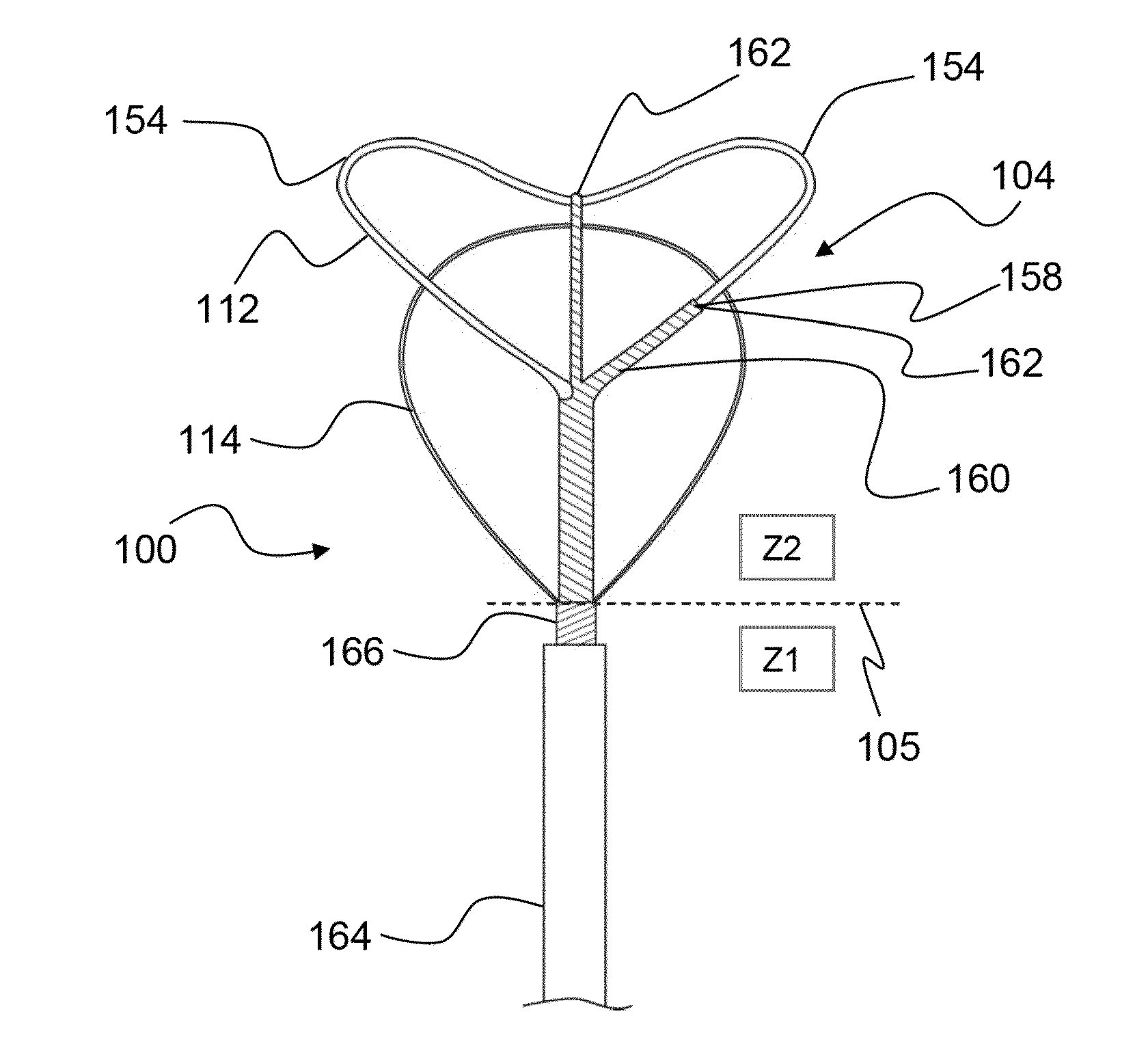
[0048]This specification discloses multiple antenna designs, systems, structures and devices, and associated methods, which illustrate various aspects of the invention. While these systems, structures and devices, and associated methods, are discussed primarily in terms of some particular clinical applications (e.g. ablating cardiac tissue to treat arrhythmias, endometrial ablation), the methods and devices disclosed herein are applicable for use in other bodily structures, as well. These systems, structures and devices, and associated methods, may be used for ablating tissue in, or adjacent to, the brain, prostate gland, portions of the urinary tract, gall bladder, uterus and other portions of the female reproductive tract, regions of the vasculature, intestines and other portions of the lower alimentary tract, stomach and other portions of the upper alimentary tract, liver and other digestive organs, lungs, skin, mucus membranes, kidneys, reproductive organs, joints, or other orga...


PUM


Abstract

The invention comprises novel microwave antennas wherein the microwave field profile generated by an antenna is tailored and optimized for a particular clinical application. The antennas disclosed herein incorporate one or more additional elements called shaping elements that use unique properties of microwaves such as interaction of a microwave field with one or more conductive or non-conductive elements to shape or redistribute the microwave field. Such shaping elements may be used to reduce the undesired backward coupling of the emitted microwave field to the transmission line. Such shaping elements may be used to increase the power efficiency of the antenna. The invention also discloses devices and methods for treating tissue with microwave energy emitted from the antennas for use in applications such as destroying a soil tissue by microwave ablation.

Description

CROSS-REFERENCE TO RELATED APPLICATIONS[0001]This application is a continuation-in-part of U.S. patent application Ser. No. 12 / 603,077, filed on Oct. 21, 2009, which claims the benefit of U.S. Provisional Patent Application No. 61 / 222,409, filed on Jul. 1, 2009, the contents of which is incorporated herein by reference in their entireties.FIELD OF THE INVENTION[0002]This invention relates to microwave antennas and devices incorporating such antennas usable for performing diagnostic and / or therapeutic procedures on or within a patient's body.BACKGROUND OF THE INVENTION[0003]Microwaves antennas are used in a variety of medical devices to treat several medical conditions. Several conditions including cardiac electrophysiological disorders, cancer, Menorrhagia, etc. are currently treated by applying microwave energy for ablating tissue. For example, microwave antennas (e.g. helical antennas) have been used in medical applications including treatment of benign prostate hyperplasia, cance...

Claims


Application Information

Patent Timeline
Patent Type & Authority Applications(United States)
IPC IPC(8): A61B18/18
CPCA61B18/18A61B18/1815A61N5/045A61B2018/1861A61B2018/00196A61B2018/1884A61B2018/1892
Inventor CHU, CHUN YIUSHROFF, KETANMODY, DINESH I.EMMONS, CLARENCEWALKE, AMRISH JAYPRAKASH
Owner MICROCUBE
Why Eureka
Try Eureka