
Modular construction mold apparatus and method for constructing concrete buildings and structures

a technology of modular construction and molds, applied in the field of building arts, can solve the problems of imposing heavy economic burdens on the community, affecting the construction efficiency of reinforced concrete facilities, etc., and achieves the effects of convenient construction of composite concrete, strong and practical, and convenient construction

Active Publication Date: 2011-01-20
JOHNSON FR +1
View PDF16 Cites 32 Cited by
  • Summary
  • Abstract
  • Description
  • Claims
  • Application Information

AI Technical Summary

Benefits of technology

"The present invention is a modular steel-frame construction mold apparatus that can be used to create large, permanently encased composite concrete and steel structures underwater and on dry land. The mold is made up of interlocking encasement panels and connectors that are integrally attached to a structural steel grillage component. The grillage provides strength and rigidity to hold the encasement assemblies in place before and during the casting process, and after casting to provide additional tensile or bending strength. The mold is designed to form void spaces for receiving wet concrete in situ, and the grillage becomes permanently embedded in the resulting structure, providing tensile strength complementing the compressive strength of concrete. The structural steel grillage also enables the construction of very wide and long horizontal structures, making construction safer, simpler, and more economical."

Problems solved by technology

Corrosion plagues all reinforced concrete structures exposed to the elements after only a few years of service reducing the load bearing capacity of a structure and imposing heavy economic burdens on the community in order to maintain them in a safe and functionally operational condition.
Another, even more costly drawback stems from the manner in which reinforced concrete facilities are constructed.
These labor intensive, time consuming tasks are repeated over and over again for each incremental unit of the structure until the last cubic yard of concrete has been cast.
Concurrently with erection of the formwork, another labor-intensive, time consuming and even more costly task is taking place: rebar installation.
The downside of this type of construction is that the steel beams supporting composite floor slabs are exposed and must be fireproofed, another labor intensive, time consuming and costly activity.
The '262 patent does not disclose how horizontal and vertical reinforcing steel rods are to be installed within the void spaces when the perforated sheet steel attachments are spaced at such close intervals.
Nor does the patent disclose how vertical wall assemblies are to be supported against hydrostatic loads when distance between the inside and outside wall assemblies forming the void space is excessive as in the case of large dimensioned pile caps, deep deck, floor and roof slabs, foundations and piers supported on piles; nor does the '262 patent disclose how the horizontal platform assemblies are to be supported to carry gravity loads associated with casting reinforced concrete slabs over very long spans without intermediary supports or shoring.
The '262 patent does not disclose how the panelized assemblies are to be erected and rebars installed when the work site is under water.
Making a work site dry in the middle of a body of water requires construction of a water tight enclosure, dewatering and other tasks prior to commencing concrete work, tasks that add considerable time and cost to a construction project.

Method used


Image

  • Modular construction mold apparatus and method for constructing concrete buildings and structures
  • Modular construction mold apparatus and method for constructing concrete buildings and structures
  • Modular construction mold apparatus and method for constructing concrete buildings and structures

Examples


Embodiment Construction

[0052]Referring now to the drawings, in which like numerals indicate like elements throughout several views and pointing out that all protruding interlocking elements integrally attached to various encasement components are configured to slidably interlock.

[0053]Corresponding housings formed within the bodies of various encasement elements are likewise identical in configuration and size and capable of slidably interlocking and engaging all protruding elements.

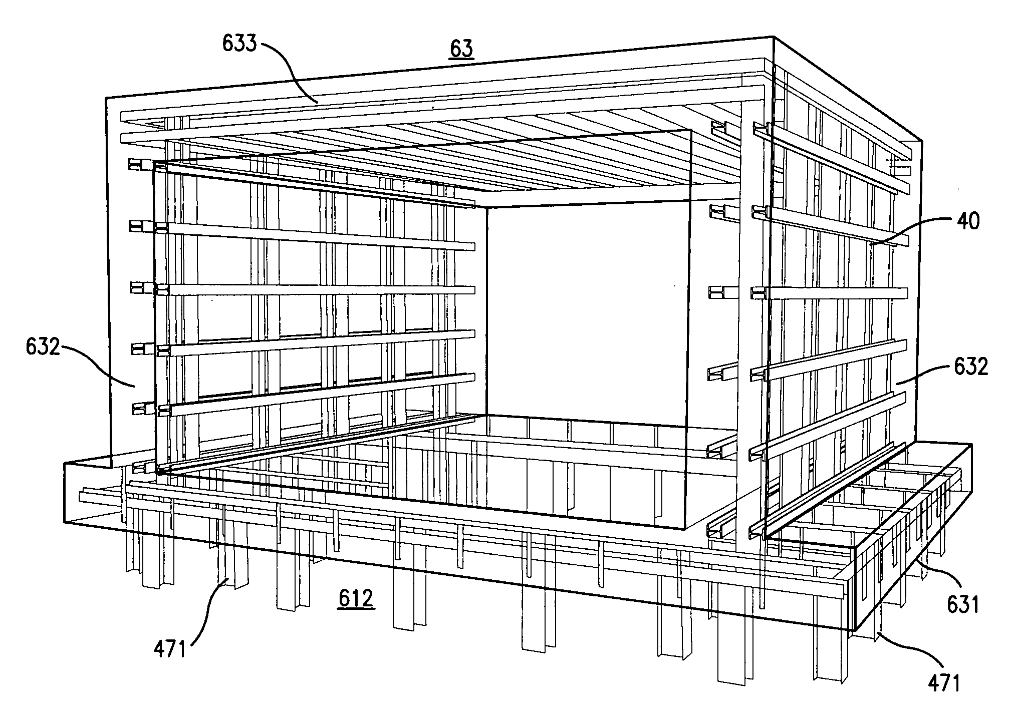
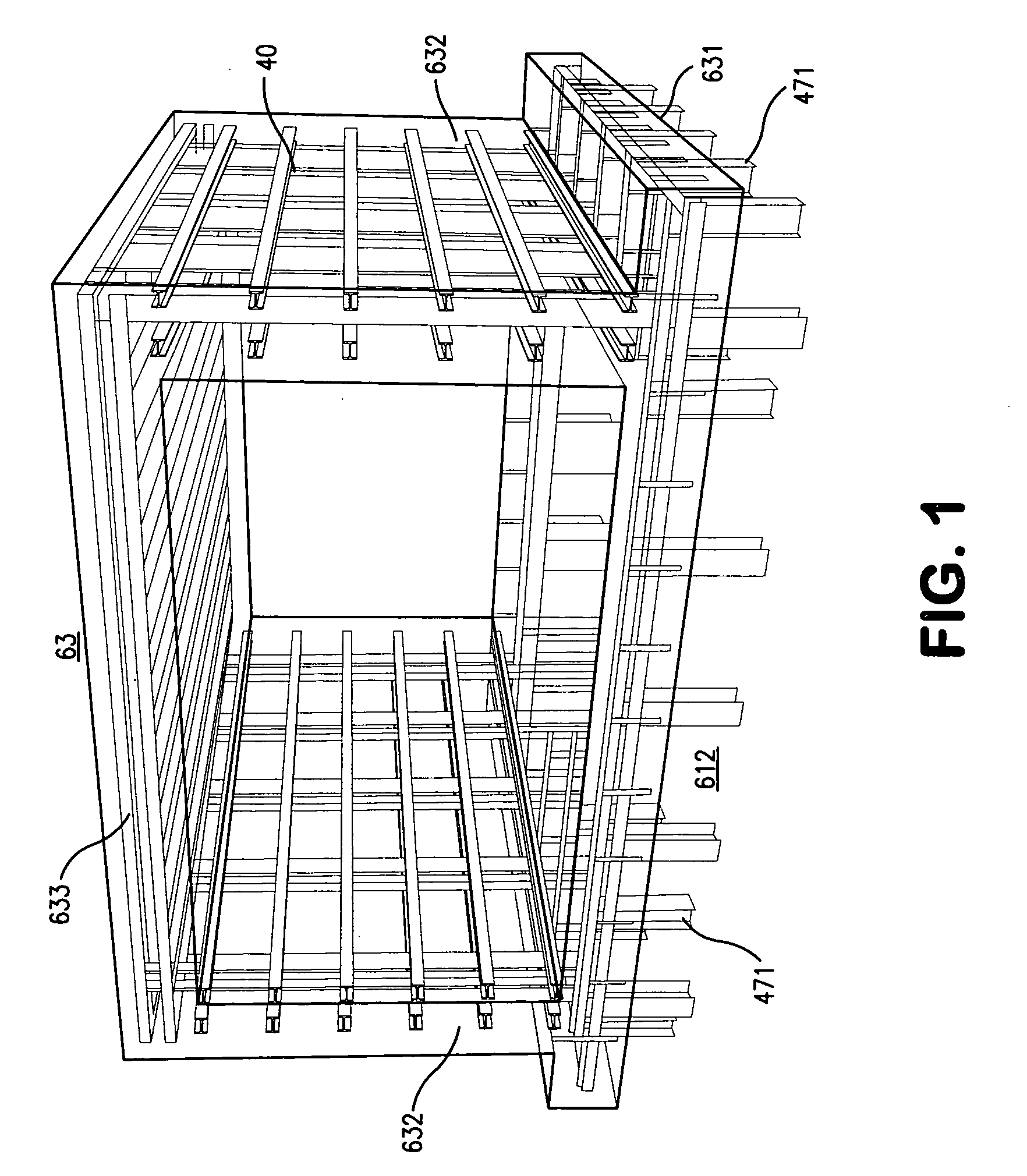
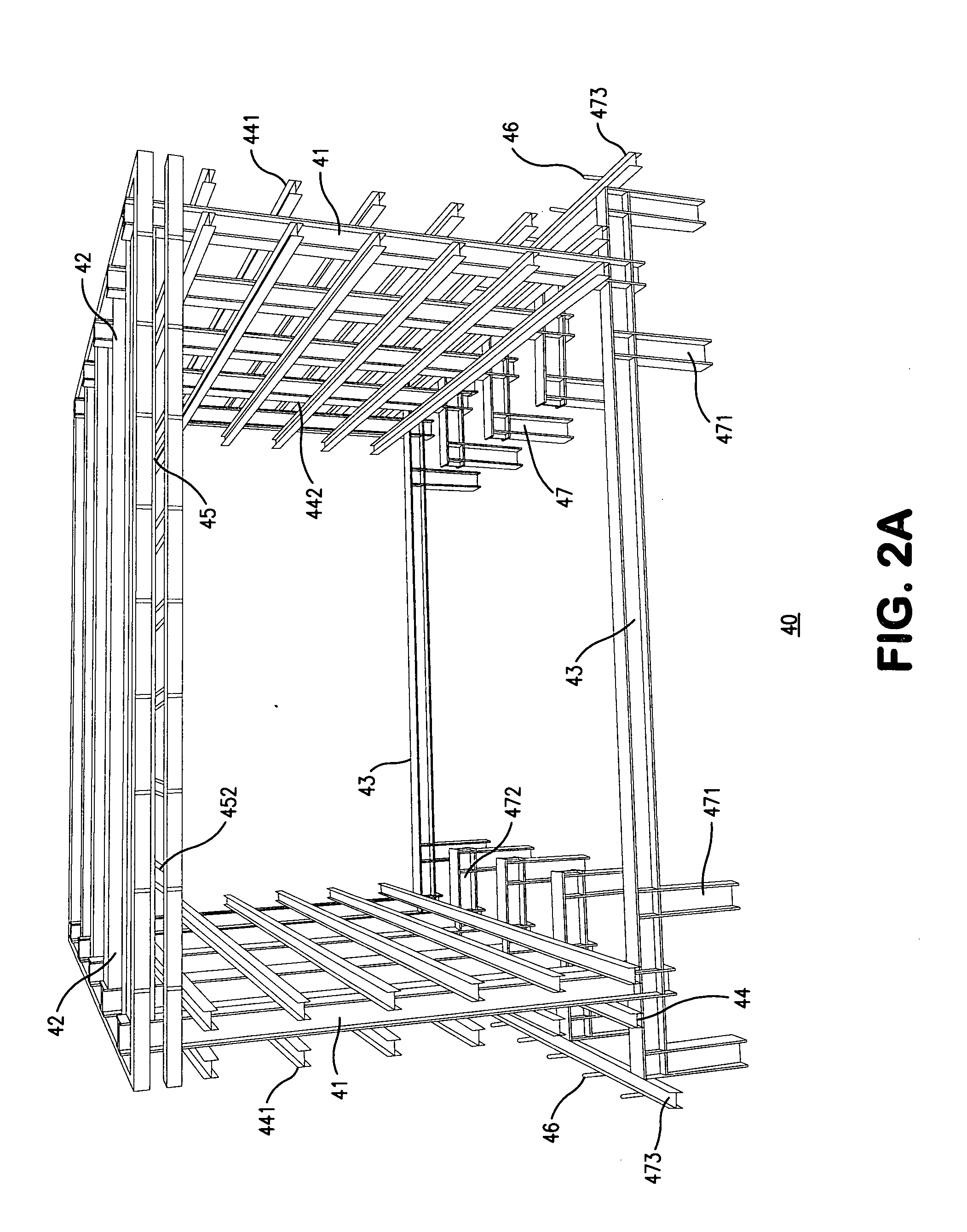
[0054]FIG. 1 shows a phantom view of an open-ended monolithic composite concrete and steel segment of a box structure 63 composed of foundation slab 631, side walls 632 and roof slab 633 formed and cast using a modular unit of a steel-framed construction mold apparatus. The encasement component of the mold apparatus is not shown for clarity. The steel grillage component 40 of said modular unit is shown embedded within the concrete segment 63. Steel bollards 471 supporting the grillage component extend downward beneath the conc...


PUM

PropertyMeasurementUnit
thicknessaaaaaaaaaa
tensionaaaaaaaaaa
compression forcesaaaaaaaaaa

Abstract

A modular steel-framed construction mold apparatus comprised of a plurality of contiguous foundation, cavity wall and roof deck void spaces defined and formed by assemblies of interlocking encasement panels and connectors integrally attached to a structural steel grillage for accepting, containing, and shaping wet concrete fill, a method for forming, casting, and encasing monolithic composite concrete and steel buildings and structures in situ using said mold apparatus, and a permanently encased monolithic composite concrete and steel structure constructed by employing the foregoing modular mold apparatus and method of concrete construction. The structural steel grillage supports the encasement assemblies before and during the casting process, becoming fully embedded within the cast concrete, and provides tensile strength complementing the compressive strength of concrete fill. The panelized encasement assemblies remain in place following casting protecting and insulating the resulting composite concrete and steel buildings and structures.

Description

FIELD OF THE INVENTION[0001]The present invention relates generally to the building arts, and more particularly to the means and methods of constructing large dimensioned monolithic composite concrete and steel buildings and structures underwater and on dry land.BACKGROUND OF THE INVENTION[0002]The present invention creates a new advance beyond the state of the art shown in U.S. Pat. No. 5,860,262 to Frank K. Johnson (“the '262 patent”), the disclosure which is incorporated herein by reference.[0003]Corrosion plagues all reinforced concrete structures exposed to the elements after only a few years of service reducing the load bearing capacity of a structure and imposing heavy economic burdens on the community in order to maintain them in a safe and functionally operational condition.[0004]Another, even more costly drawback stems from the manner in which reinforced concrete facilities are constructed. A temporary wood-sheathed structure, called formwork must be fabricated on site, er...

Claims


Application Information

Patent Timeline
Patent Type & Authority Applications(United States)
IPC IPC(8): E04B1/19E04B1/00E04B1/16
CPCE04B1/14E04B1/161E04B2002/867E04B2/8652E04B2/8635B28B1/14B28B23/02E02D29/06E04B1/167E02D2250/0007E02D2250/0023E02D2250/0061E02D2300/002E02D2300/0029E04B2103/02E04B2103/06E04C5/06
Inventor JOHNSON, FRANKKIRMANI, MINHAJ
Owner JOHNSON FR
Learn More