
Immobilization apparatus

a technology of immobilization apparatus and nozzle, which is applied in the direction of electrostatic spraying apparatus, electrostatic heating/cooling, coating, etc., can solve the problems of inability to form thin films, and inability to form small amounts of films, so as to facilitate the generation of microparticles and reduce particle size.

Inactive Publication Date: 2011-01-27
TANIOKA AKIHIKO +2
View PDF10 Cites 12 Cited by
  • Summary
  • Abstract
  • Description
  • Claims
  • Application Information

AI Technical Summary

Benefits of technology

[0011]It is, therefore, an object of the invention to solve the above problems and provide a technique for atomizing and immobilizing a sample solution (aqueous solution, inorganic or organic solvent solution) containing a substance being easily denaturalized and transubstantiated such as a biologic polymer, an organic polymer, an inorganic substance or the like (e.g., protein, dye compound, organic compound, functional polymer, etc.) extremely rapidly without damaging its activity (biological activity, etc.) and function.Means for Solving Problem
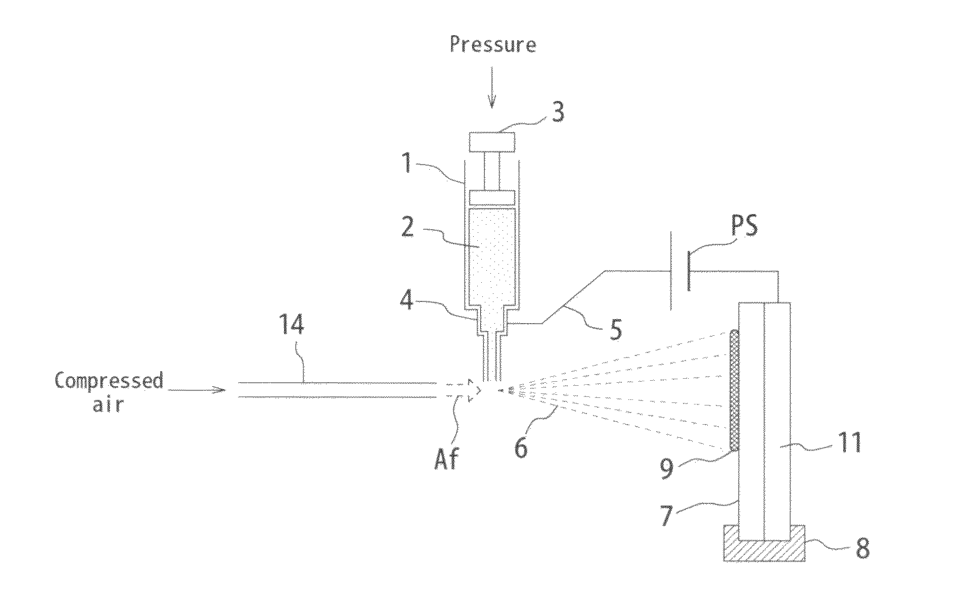
[0054]Moreover, by the crash of airflow, a solution at the tip portion of a capillary receives the crash energy, and becomes a number of micro liquid drops (liquid particles, particulate substances) to diffuse. Simultaneously, since a high voltage is applied to the solution in advance, the liquid drops are charged and by the electrostatic force, become a number of smaller liquid drops to diffuse. By these crash energy and electrostatic force, the atomized liquid drops change into finer liquid drops in a short time while flying. Namely, these charged fine particulate substances flying out vapor the solvent and water and decrease in particle size while flying towards a grounded substrate or an electrode with the opposite polar character. Moreover, the particulate substances are divided into smaller particulate substances by the electrostatic repulsion inside thereof. Then, it is immobilized on the substrate in a dry state as a deposit. Thus, it is possible to atomize a solution as charged fine particulate substances. In addition, along with the atomization by the electrostatic force of voltage application and the airflow, atomization only by the electrostatic force sometimes occurs simultaneously in the exhaust outlet.

Problems solved by technology

Although a variety of apparatus and methods for forming such a thin film have been invented and practiced heretofore, the conventional apparatus and methods are not necessarily suitable for forming a thin film by immobilizing a biologic polymer, a functional polymer or the like while maintaining its activity for the following reasons.
However, since these apparatus are exposed to a plasma or a high heat under a strong vacuum, it is hardly possible to form a thin film by immobilizing a biologic polymer, an organic polymer and the like while maintaining the activity.
The apparatus, however, requires a huge amount of liquid for the spray by pressurized air and incurs a lot of waste, so is not suitable for forming of a small amount of film of functional polymer or biologic polymer.
Moreover, since the diameter of an atomized liquid drop is extremely large in the spray by pressurized air, the liquid drop reaches the substrate without being dried.
Thereby, it takes a long time to dry on the substrate, and a biologic polymer, which is easily denaturalized, is liable to lose the activity in the drying process taking such a long time.
Therefore, it is difficult to form a film by immobilizing such a substance being easily denaturalized while maintaining the activity with the electrostatic coating apparatus.
This apparatus also has a lot of problems in forming a film of biologic polymer being more likely to lose the activity, an expensive organic polymer or the like for the same reason, i.e. since the drying time takes long or a lot of materials are wasted.
However, it is also difficult to form a thin film by immobilizing a functional polymer or the like while maintaining the activity by this method for the same reason as above, i.e. since the drying time takes long.
There is, however, a problem in this method that it is difficult to spray a solution with high electric conductivity and the kinds of formable thin films are limited (See Non-patent Document 1: Analytical Chemistry 73, p 2183-2189, 2001).
Particularly, a biologic polymer such as a protein is generally dissolved in a buffer solution for keeping pH constant and the electric conductivity is large to be not less than approximately 1000 μS, thereby it is difficult to form a spot or a film by immobilizing it as it is by the ESD method.
Also, since a protein and the like lose the activity rapidly in a short time when a stabilizer such as a buffer is removed, the operation for forming a thin film needs to be conducted in a short time and the operating efficiency is down in the case of such a sample.
Moreover, there is a problem in that the activity deteriorates even though a thin film can be formed.
Furthermore, since the ESD method requires a sample to be almost completely dissolved in a solution for passing through a hole on the tip of a capillary, it is difficult to use a sample being difficult to be dissolved, such as a particle.

Method used


Image

  • Immobilization apparatus
  • Immobilization apparatus
  • Immobilization apparatus

Examples


embodiment 1

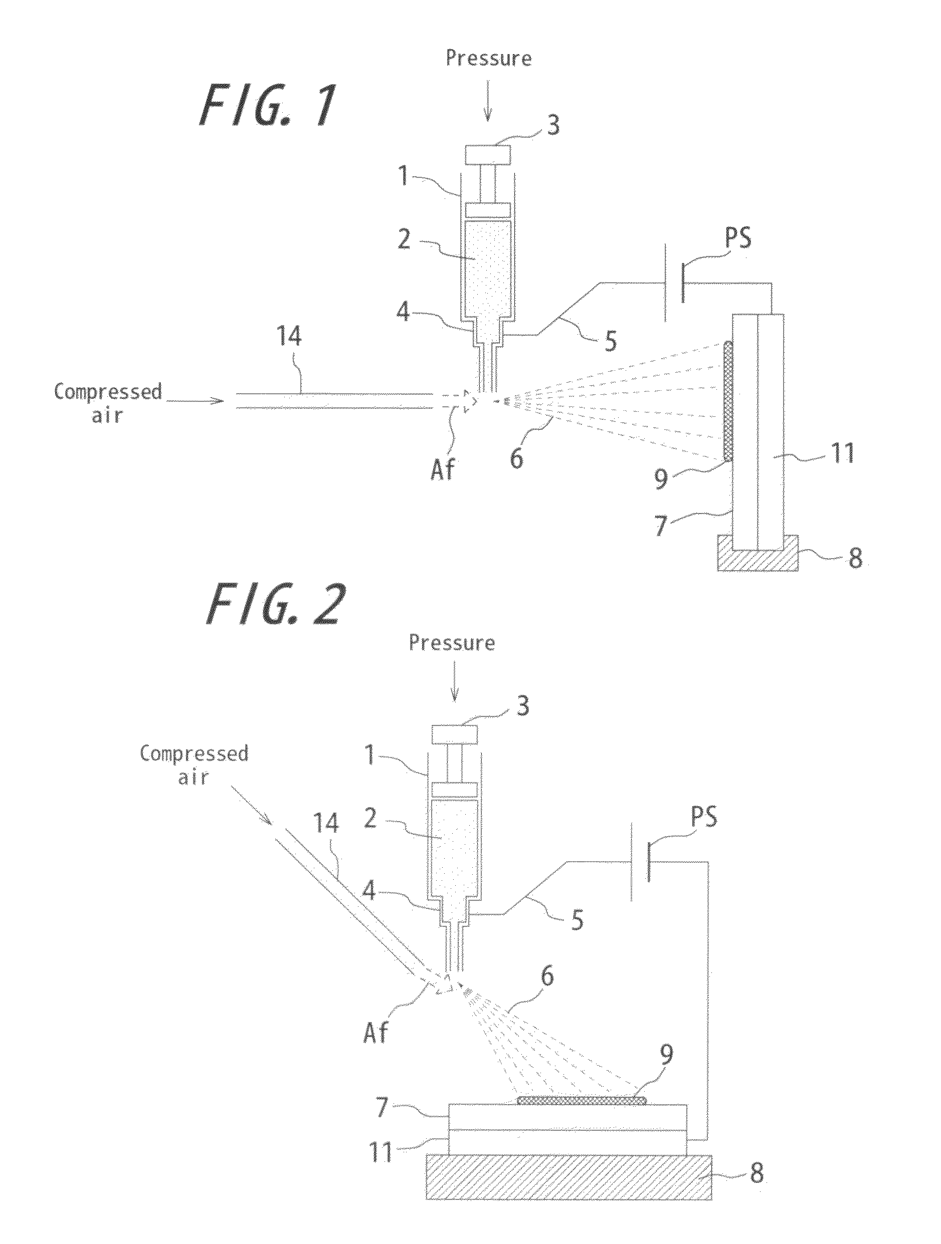
[0080]FIG. 1 is a conceptual view showing a basic configuration of an immobilization apparatus according to one embodiment of the invention. As shown, a syringe (container) 1 stores a sample solution 2. The sample solution 2 is, for example a biopolymer solution such as a protein, an organic polymer solution, a polymer solution or the like.

[0081]Also, the sample solution within the syringe 1 receives extrusion pressure at a plunger (exhausting means) 3. The extrusion pressure is applied by a stepping motor and a feed screw mechanism (not shown). The extrusion pressured sample solution 2 increases the inner pressure within the syringe 1, and is exhausted from the tip of a nozzle 4. As mentioned above, by providing a regulating mechanism (stepping motor and feed screw mechanism) for regulating the exhaust rate of a sample solution, it becomes possible to regulate the exhaust rate as appropriate. By such a regulation, it becomes possible to obtain a dry deposit instead of a wet deposit...

embodiment 2

[0088]FIG. 2 is a conceptual view showing a basic configuration of an immobilization apparatus according to another embodiment of the invention. Hereinafter, in each figure, the same elements are labeled with the same reference mark and the explanation thereof is omitted. The apparatus in FIG. 2 is different from the one in FIG. 1 in the point that while the direction of the high velocity airflow Af spouts from immediately lateral to a nozzle in FIG. 1, it is configured to spout from obliquely upside in FIG. 2. Atomization is likewise possible from obliquely upside or immediately above as the direction of the airflow Af. In FIG. 2, the airflow Af is crashed into the sample solution 2 positioned in an exhaust outlet EXT from obliquely upside avoiding the syringe 1 to deposit the sample on the level substrate 7. By such an arrangement, it is possible to hit the tip portion of the nozzle 4 with the airflow Af avoiding the syringe 1 so as not to lose the momentum of the airflow Af for e...

embodiment 3

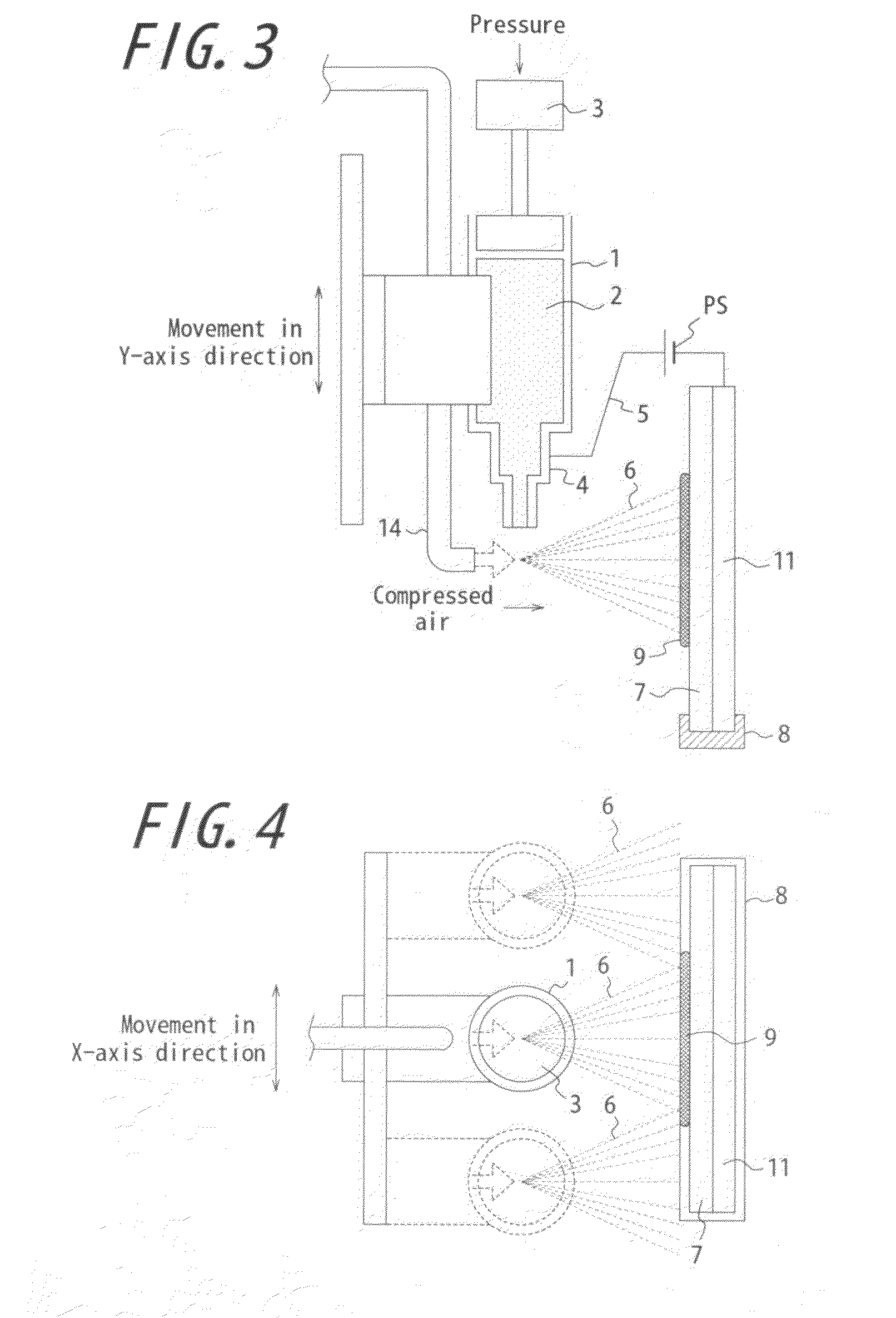
[0089]FIGS. 3 and 4 are conceptual views each showing a basic configuration of an immobilization apparatus according to another embodiment of the invention. The apparatus shown in FIGS. 3 and 4 are different from the apparatus shown in FIG. 1 mainly in that the syringe 1 and the tube 14 are configured to be driven on a planar surface parallel to the planar surface of the substrate 7. FIG. 3 explains a configuration in which the syringe 1 and the tube 14 are drive in the Y-axis direction (vertical direction) and FIG. 4 explains a configuration in which the syringe 1 and the tube 14 are drive in the X-axis direction (horizontal direction). As seen from the figures, in this embodiment, the syringe 1 and the tube 14 are provided so that they can be independently driven by a driving means in the Y-axis direction and a driving means in the X-axis direction. The syringe 1 and the tube 14 change a position where the particulate substance 6 is deposited by changing the relative positional re...


PUM


Abstract

The invention is an immobilization apparatus comprising: a container (1) having a nozzle (4) formed for exhausting a solution; a charging means (PS, 5, 4) for charging the sample solution within the container; and an airflow generating means for generating airflow (Af) crashing into the sample solution. The immobilization apparatus is configured to operate the charging means and the airflow generating means simultaneously, atomize the solution into microparticulate substances charged while maintaining its activity and functionality by the electrostatic force due to the charge of the sample solution charged by the charging means and the crash energy due to the crash of the airflow generated by the airflow generating means into the sample solution, and exhaust it from the exhaust outlet (4), and the charged microparticulate substances are deposited on a substrate (7) by the electrostatic force.

Description

TECHNICAL FIELD[0001]This invention relates to an immobilization apparatus.BACKGROUND ART[0002]In recent years, a thin film of immobilized biologic polymer, functional polymer, organic polymer or the like has been broadly used in an extraordinary variety of applications in high demand such as analytical instruments like a biochip, a biosensor and so on, various display devices, an optical element, a semiconductor element and the like. Although a variety of apparatus and methods for forming such a thin film have been invented and practiced heretofore, the conventional apparatus and methods are not necessarily suitable for forming a thin film by immobilizing a biologic polymer, a functional polymer or the like while maintaining its activity for the following reasons. For example, a spattering apparatus, an EB resistance heating deposition apparatus, a CVD apparatus and the like are put into practical use for forming a thin film of metal or a thin film of inorganic compound. However, s...

Claims


Application Information

Patent Timeline
Patent Type & Authority Applications(United States)
IPC IPC(8): B05B5/03
CPCB05B5/03B05B5/032B05B7/0075B05B7/0807B05B5/087B05B5/001
Inventor TANIOKA, AKIHIKOINOUE, KOZONITTA, KAZUYATAMARU, MASARU
Owner TANIOKA AKIHIKO
Learn More