
Plasma welding process and outer gas for use in the plasma welding process

Active Publication Date: 2011-01-27
TAIYO NIPPON SANSO CORP
View PDF4 Cites 25 Cited by
  • Summary
  • Abstract
  • Description
  • Claims
  • Application Information

AI Technical Summary

Benefits of technology

[0038]According to the first and second aspects of the present invention, since plasma welding of a stainless steel is conducted by using a welding torch in which a center gas comprising an inert gas is allowed to flow and a mixed gas containing 0.5 to 2% by volume of a carbon dioxide gas in an inert gas is allowed to flow as an outer gas, a deep weld can be created and the penetration bead can be stabilized. For this reason, there is no need of applying a backing metal, and a stainless steel material having a thickness of 8 mm to 12 mm can be welded. As a result, the cost for the production and the installation of the backing metal (made of copper) becomes unnecessary. In addition, it becomes possible to readily and favorably weld even an object to be welded which can not be applied with a backing metal, such as a pipe or a vessel.
[0039]According to the third to sixth aspects of the present invention, since plasma welding of a carbon steel is conducted by using a welding torch in which a center gas comprising an inert gas is allowed to flow and a mixed gas containing 0.5 to 2% by volume of a carbon dioxide gas in argon or a mixed gas containing 0.5 to 6% by volume of oxygen in argon is allowed to flow as an outer gas, a deep weld can be created, keyhole welding can be conducted, and the penetration bead can be stabilized. For this reason, there is no need of applying a backing metal, and a carbon steel material having a thickness of 6 mm to 10 mm can be welded. As a result, the cost for the production and the installation of the backing metal (made of copper) becomes unnecessary. In addition, it becomes possible to readily and favorably weld even an object to be welded which can not be applied with a backing metal, such as a pipe or a vessel.

Problems solved by technology

However, in a conventional plasma welding process, it has been difficult to stably create a penetration bead upon welding of a stainless steel having a thickness of 8 mm or thicker, or a carbon steel having a thickness of 6 mm or thicker, which leads to a problem in that, due to the influence of gravity, the molten metal can not bear its own weight and the shape of the penetration bead can not remain stable.
Moreover, if the penetration bead can not remain stable, the finish of the surface bead is affected, which leads to an inconvenient situation in that readjustment has to be done.

Method used


Image

  • Plasma welding process and outer gas for use in the plasma welding process
  • Plasma welding process and outer gas for use in the plasma welding process
  • Plasma welding process and outer gas for use in the plasma welding process

Examples


first and second embodiments

of this Invention

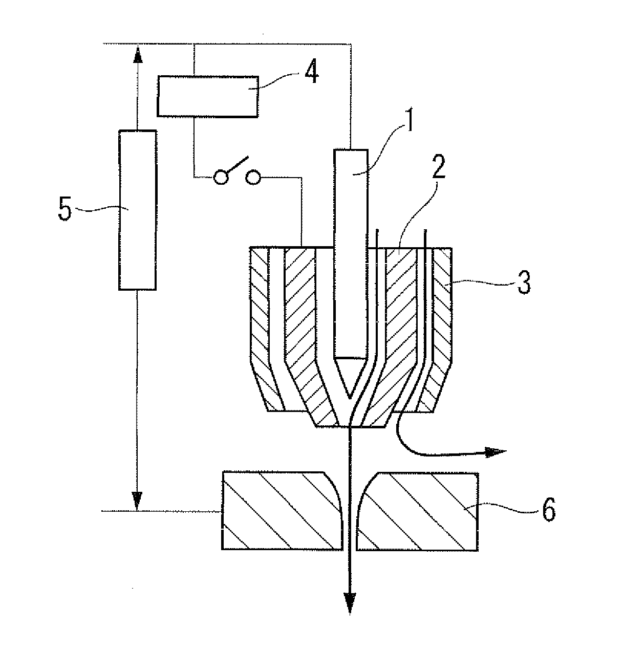
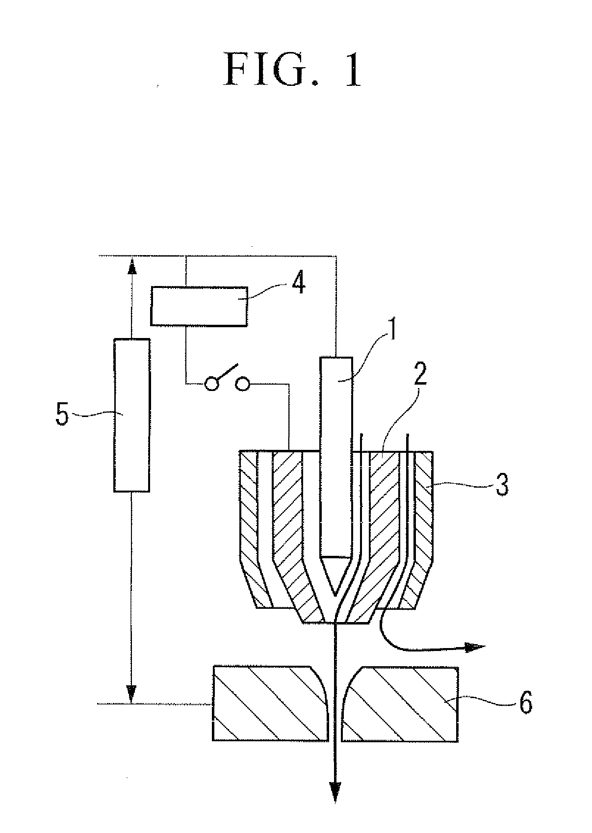
[0045]In the first and second embodiments of this invention, when conducting plasma welding with use of, for example, a plasma welding torch shown in FIG. 1, a center gas comprising an inert gas such as argon or helium, or a mixed gas thereof, is allowed to flow into a gap between the tungsten electrode 1 and the insert tip 2, and an outer gas comprising a mixed gas containing 0.5 to 2% by volume, preferably 0.6 to 2% by volume, of a carbon dioxide gas, and 98 to 99.5% by volume, preferably 98 to 99.4% by volume, of an inert gas such as argon or helium, or a mixed gas containing argon and helium, is allowed to flow into a gap between the insert tip 2 and the shield cap 3.

[0046]The first and second embodiments correspond to the first and second aspects mentioned above.

[0047]In the first and second embodiments of this invention, such a combination of the center gas and the outer gas provides an effect of creating a deep weld, and enabling to stabilize a penetration be...

sixth embodiments

Third to Sixth Embodiments of this Invention

[0063]In the third to sixth embodiments of this invention, when conducting plasma welding of a carbon steel as a material to be welded with use of, for example, a plasma welding torch shown in FIG. 1, a center gas comprising an inert gas such as argon or helium, or a mixed gas thereof, is allowed to flow into a gap between the tungsten electrode 1 and the insert tip 2, and an outer gas comprising either one of the following two types of mixed gases is allowed to flow into a gap between the insert tip 2 and the shield cap 3.

[0064]1) a mixed gas containing 0.5 to 2% by volume, preferably 0.5 to 1% by volume, of a carbon dioxide gas with the balance of argon

[0065]2) a mixed gas containing 0.5 to 6% by volume, preferably 0.5 to 3% by volume, of oxygen with the balance of argon

[0066]The third to sixth embodiments correspond to the third to sixth aspects mentioned above.

[0067]In the third to sixth embodiments of this invention, such a combinatio...

example 1

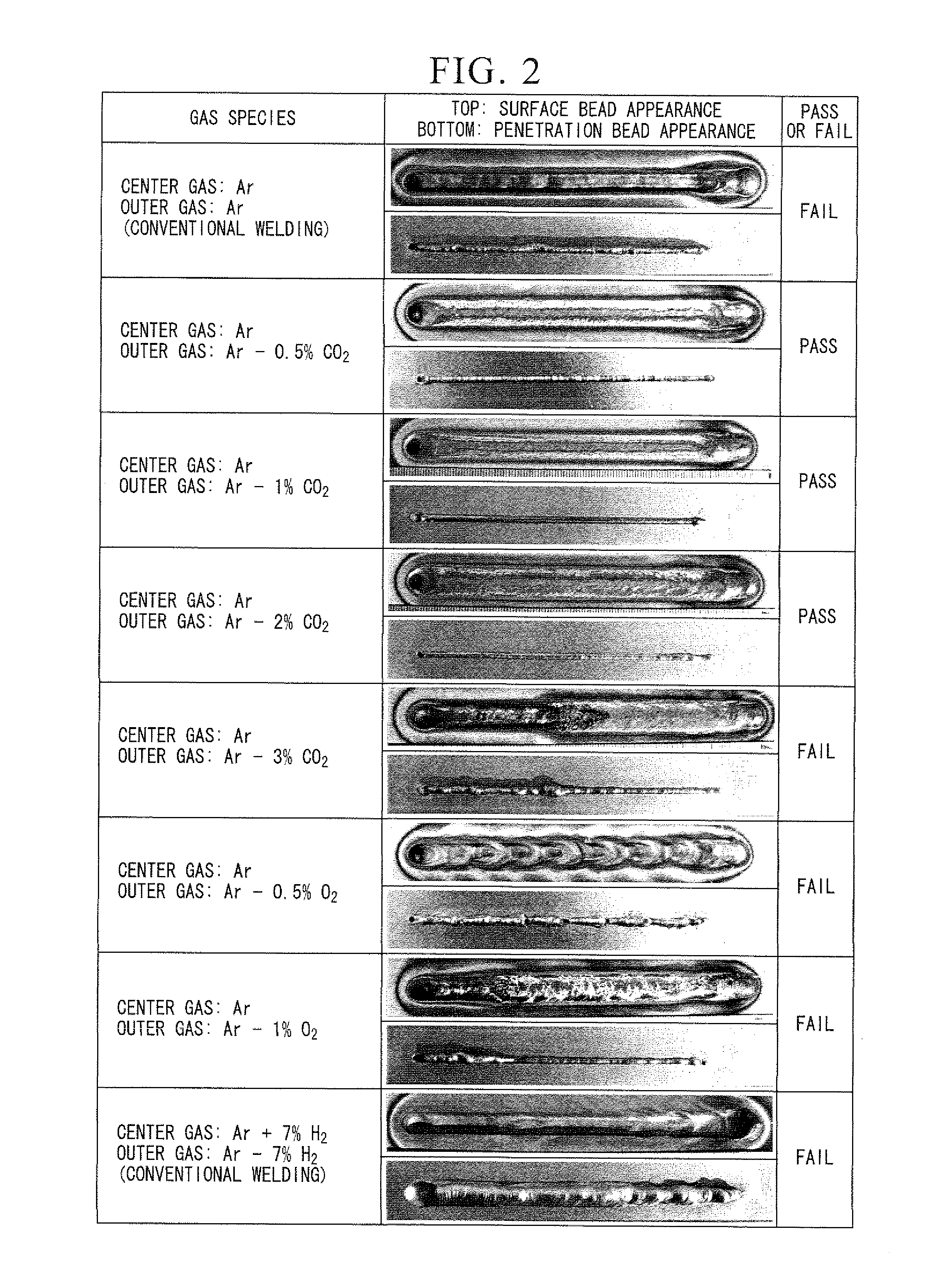
[0083]Plasma welding was conducted by the bead-on-plate method under the following welding conditions, using a stainless steel plate having a thickness of 8 mm, and the stability of the penetration bead was examined.

[0084]Welding mode: plasma welding (non-consumable electrode welding)

[0085]Welding base metal: SUS304 (in a thickness of 8 mm)

[0086]Welding method: plasma welding process (downward posture)

[0087]Electrode: 2% lanthanum oxide-containing tungsten φ 4.8 mm

[0088]Distance between center nozzle and base material: 3.5 mm

[0089]Inclination angle of torch: angle of advance at 20°

[0090]Welding current: peak current=120 A, Base current=50 A

[0091]Welding rate: 6 cm / min

[0092]Pulse width: 50%

[0093]Pulse frequency: 50 Hz

[0094]Inner diameter of nozzle: 2 mm

[0095]Backing metal: Not used

[0096]The combination of the center gas and the outer gas as shown in 1) to 4) below was used. The symbol % means percent by volume in all cases.

[0097]1) Center gas: 100% Ar; Outer gas: a mixed gas containi...


PUM

PropertyMeasurementUnit
Percent by volumeaaaaaaaaaa
Fractionaaaaaaaaaa

Abstract

An outer gas for plasma welding of the present invention is used in plasma welding of a stainless steel with use of a plasma welding torch in which an insert tip (2) is provided in the periphery of a tungsten electrode (1), a shield cap (3) is provided in the periphery of this insert tip (2), a front end part of the tungsten electrode (1) is located inside from a front end part of the insert tip (2), a center gas comprising an inert gas is allowed to flow into a gap between the tungsten electrode (1) and the insert tip (2), and the outer gas is allowed to flow into a gap between the insert tip (2) and the shield cap (3), wherein the outer gas is a mixed gas containing 0.5 to 2% by volume of a carbon dioxide gas with the balance of an inert gas.

Description

TECHNICAL FIELD[0001]The present invention relates to a plasma welding process and an outer gas for use in the plasma welding process, in particular to a plasma welding process and an outer gas with which a stable penetration bead can be created even in a thick material to be welded.[0002]Priority is claimed on Japanese Patent Application No. 2008-080650, filed Mar. 26, 2008, and Japanese Patent Application No. 2009-026121, filed Feb. 6, 2009, the contents of which are incorporated herein by reference.BACKGROUND ART[0003]A plasma welding process is classified in the category of non-consumable electrode welding processes, as well as a TIG welding process. The plasma welding process offers a greater heat concentration as compared to the TIG welding process, and thus is capable of a high speed welding with a narrow bead width and less distortion.[0004]Moreover, the plasma welding process is capable of keyhole welding which is a one-side penetration welding process by using a plasma arc...

Claims


Application Information

Patent Timeline
IPC IPC(8): B23K10/02C09K3/00
CPCB23K9/16B23K35/38B23K35/0261B23K10/02
Inventor WADA, KATSUNORI
Owner TAIYO NIPPON SANSO CORP
Learn More