
Electronic circuit board and power line communication apparatus using it

a technology of electrical circuit board and power line communication device, which is applied in the direction of powerline communication application, high frequency circuit adaptation, and association of printed circuit non-printed electric components, etc., can solve the problems of characteristic degradation and noise occurring in digital circuits, and achieve the effect of reducing the noise of the second circuit on the first circuit, shortening the line length of the conducting path, and reducing the noise occurring

Inactive Publication Date: 2011-01-27
PANASONIC CORP
View PDF13 Cites 15 Cited by
  • Summary
  • Abstract
  • Description
  • Claims
  • Application Information

AI Technical Summary

Benefits of technology

[0017]According to the invention, the first circuit for performing analog signal processing is mounted on one end and the second circuit for performing digital signal processing is mounted on the opposite end of the first face, whereby the first circuit is placed at a distance from the second circuit, so that the effect of noise of the second circuit on the first circuit can be decreased. Further, the connection part is mounted on the projection face of the second circuit on the second face, whereby it is made possible to shorten the line length of the conducting path for electrically connecting the second circuit and the connection part, so that it is made possible to decrease noise occurring from the conducting path. Accordingly, it is possible to decrease the effect of noise on the first circuit.

Problems solved by technology

Thus, there is a problem in that noise occurring in the digital circuit invites characteristic degradation of the analog circuit and hitherto various measures have been considered.

Method used


Image

  • Electronic circuit board and power line communication apparatus using it
  • Electronic circuit board and power line communication apparatus using it
  • Electronic circuit board and power line communication apparatus using it

Examples


embodiment 1

[0104]In Embodiment 1, a PLC modem 100 that houses a PLC module used for high-speed power line communications (PLC) in a housing 101 will be described as an electronic circuit board. The PLC modem 100 is an example of a power line communication apparatus, and the power line communication apparatus may be an electric device containing a PLC modem.

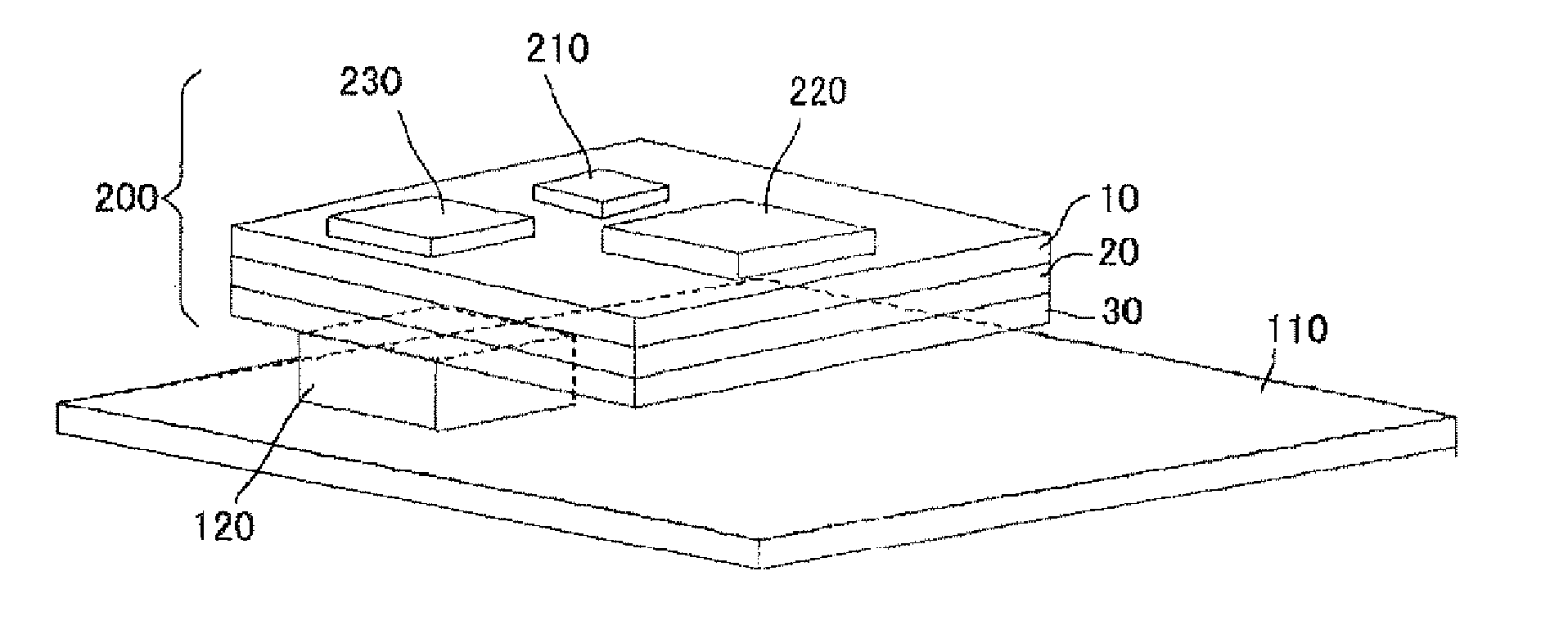
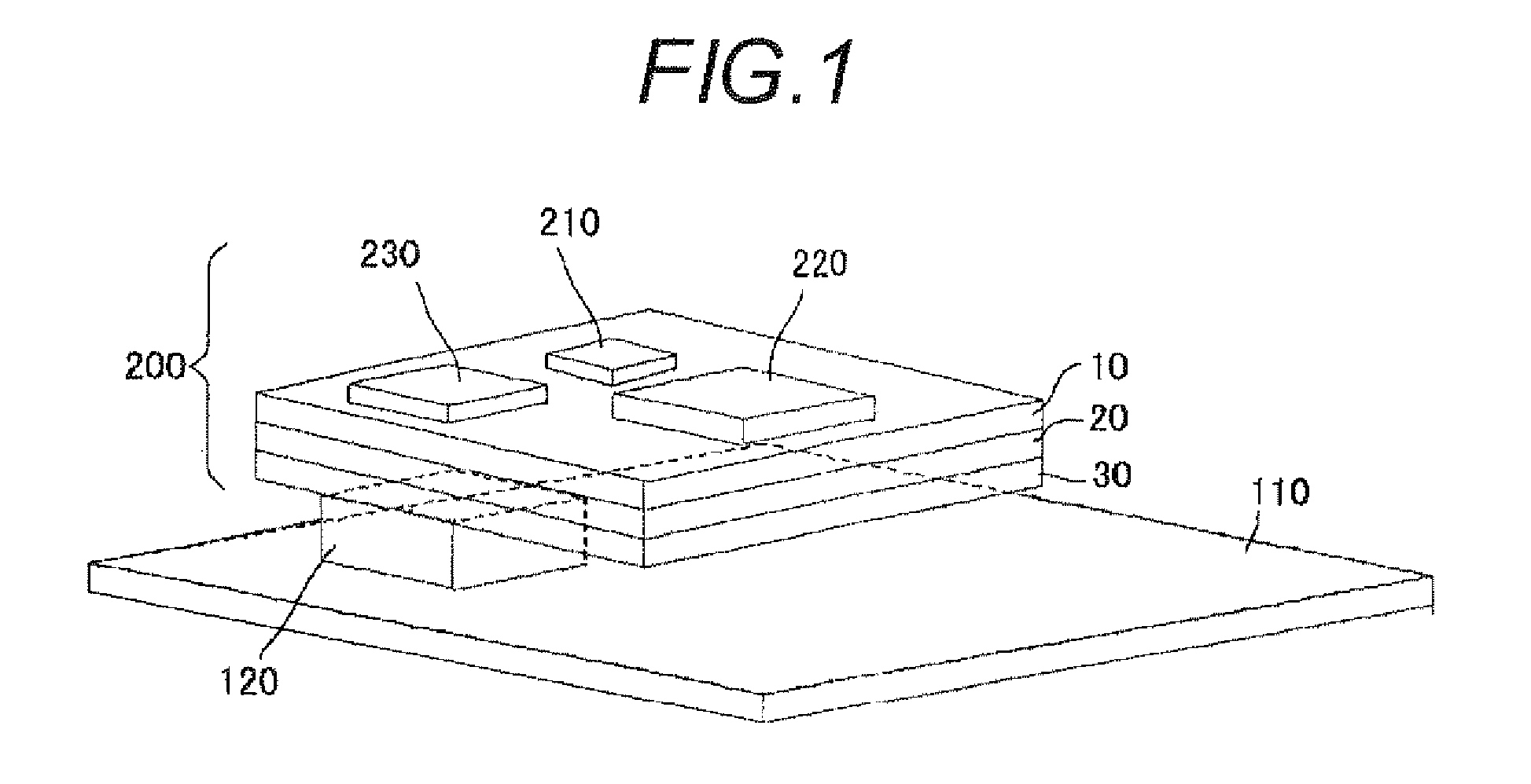
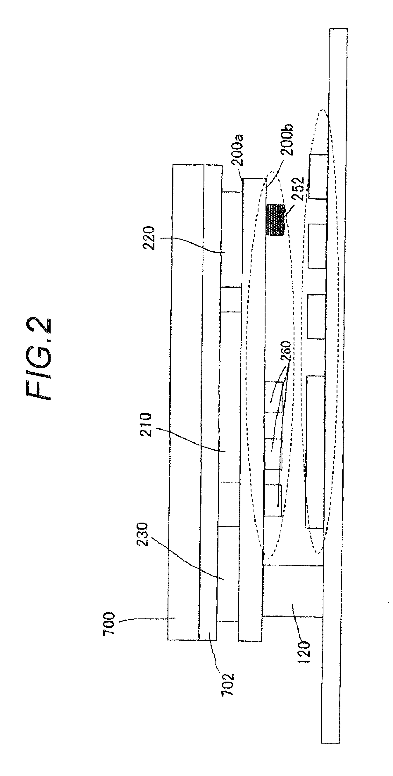
[0105]In the embodiment, two electronic circuit boards attached to a mother board 110 through a connector 120 as a connection part configure a PLC circuit module 200 as shown in a perspective view of FIG. 1 and a cross-sectional schematic drawing of FIG. 2. That is, digital components such as an Ethernet (registered trademark) PHY IC 230 for modulating and demodulating a signal transmitted through an Ethernet (registered trademark) cable, a PLC IC 210 for modulating and demodulating a PLC signal (multicarrier signal) transmitted through a power line, and an AFE IC (Analog Front End IC) 220 for performing necessary signal processing for the P...

embodiment 2

[0195]Next, Embodiment 2 will be described. In Embodiment 1 described above, to house the module in the housing 101, the heat slinger is attached through rubber as an elastic body having good heat conductivity. However, the module may be housed in the housing 101 as it is through no elastic body and no heat slinger as shown in FIG. 15.

embodiment 3

[0196]Next, Embodiment 3 will be described.

[0197]In the embodiment, as shown in FIG. 16, metal plates 40 and 41 for radiation are stacked through composite sheets 42 and 43 on the upper and lower faces of the PLC module provided in Embodiment 1 described above to form a PLC module, whereby radiation as the module is performed effectively. Others are formed like the PLC module of Embodiment 1 shown in FIG. 1. Parts identical with those in FIG. 1 are denoted by the same reference numerals in FIG. 16. A connector 120 as a connection part does not exist in the cross section and thus is not shown although it appears when the module is cut in another cross section.

[0198]According to the configuration, when the circuit integration degree increases, heat slingers are formed at the same time on the upper and lower faces, whereby the radiation area can be widened and a small-sized and low-cost module can be configured.

[0199]The case where the number of metal plates for radiation is two has be...


PUM


Abstract

A highly reliable electronic circuit board for suppressing propagation of noise and a power line communication apparatus using it are provided. An electronic circuit board of the invention is connected to a different electronic circuit board and including a first board having a first face and a second face opposed to the first face and a second board having a third face and a fourth face opposed to the third face. The electronic circuit board includes a first circuit mounted on one end of the first face for performing analog signal processing; a second circuit mounted on another end of the first face for performing digital signal processing; a junction layer provided between the second face and the third face for jointing the first board and the second board; a built-in electronic component built into the junction layer; a connection part mounted on the fourth face and to be connected to the different electronic circuit board; and a first conducting path for electrically connecting the second circuit and the connection part, wherein the connection part is mounted at a position overlapping projection projecting the second circuit onto the fourth face from a vertical direction relative to the first face.

Description

TECHNICAL FIELD[0001]The present invention relates to an electronic circuit board and a power line communication apparatus using it, and in particular to the mounting structure and radiation measures of a semiconductor integrated circuit used in an environment in which noise countermeasures are strict such as high-speed power line communications (PLC).BACKGROUND ART[0002]With requirement for miniaturization of electronic components, in a circuit module in which semiconductor integrated circuits and circuit components are installed, it is necessary to install a large number of semiconductor circuit chips and circuit components and a demand for effective utilization of a wiring space and a mount space grows.[0003]Particularly, a signal used in an optical communication field is a digital signal and thus an analog signal connected to output of a light reception element and a digital circuit installed for the purpose of for synchronizing a reception signal, etc., are mixed. Thus, there i...

Claims


Application Information

Patent Timeline
Patent Type & Authority Applications(United States)
IPC IPC(8): H05K7/00H05K1/11
CPCH04B3/54H05K2203/061H04B2203/5445H04B2203/5483H05K1/0216H05K1/0237H05K1/141H05K1/181H05K1/186H05K3/4611H05K2201/042H05K2201/09972H05K2201/10189H05K2201/10515H05K2201/10689H04B2203/54
Inventor KAWANO, HIROSHIYAMAGUCHI, SHUICHIRONARUSE, TAKUMIYAMAUCHI, TOSHIHIRO
Owner PANASONIC CORP
Learn More