Water based environmental barrier coatings for high temperature ceramic components

a technology of ceramic components and environmental barriers, applied in water-setting substances, blade accessories, machines/engines, etc., can solve the problems of unsatisfactory effects, inability to stabilize silicon oxide in high-temperature steam, and increased durability of high-temperature engine components

Inactive Publication Date: 2011-02-03
GENERAL ELECTRIC CO
View PDF20 Cites 55 Cited by
  • Summary
  • Abstract
  • Description
  • Claims
  • Application Information

AI Technical Summary

Benefits of technology

[0006]Accordingly, there remains a need for environmental barrier coatings to protect CMCs from the high temperature steam environments present in gas turbine engines.

Problems solved by technology

However, as operating temperatures increase, the high temperature durability of the components of the engine must correspondingly increase.
Additionally, silicon oxide is not stable in high temperature steam, but rather, can be converted to volatile (gaseous) silicon hydroxide species.
Unfortunately, there can be some undesirable issues associated with standard, industrial coating processes such as plasma spray and vapor deposition (i.e. chemical vapor deposition, CVD, and electron beam physical vapor deposition, EBPVD) currently used to apply EBCs.

Method used


Image

  • Water based environmental barrier coatings for high temperature ceramic components
  • Water based environmental barrier coatings for high temperature ceramic components
  • Water based environmental barrier coatings for high temperature ceramic components

Examples


example

Example 1

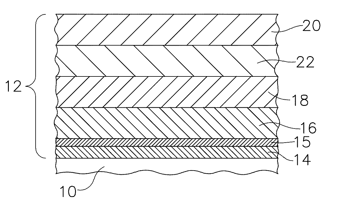
[0081]A silicon bond coat was applied to a SiC—SiC CMC using a conventional air plasma spray process. Next, a primary transition material slurry was made by first mixing yttrium disilicate powder, aluminum oxide powder, water, polyacrylic acid-polyethylene oxide copolymer, Surfynol 502®, and glycerin in a plastic container, along with enough 0.25 inch (6.35 mm) diameter, cylindrical alumina media to line the bottom of container. This mixture was placed on a roller mill for 15 hours. After taking the container off of the roller mill, the alumina media was removed. Xanthan gum was then added and the mixture was shaken for 15 minutes using a paint shaker. Finally, Rhoplex® HA8 emulsion was added and the container was placed back onto the roller mill for 1 hour (without media).

[0082]The resulting primary transition material slurry (Slurry A) consisted of 65.87% yttrium disilicate (primary transition material), 4.85% aluminum oxide (sintering aid), 6.59% polyacrylic acid-polyeth...


PUM

PropertyMeasurementUnit
thicknessaaaaaaaaaa
thicknessaaaaaaaaaa
operating temperaturesaaaaaaaaaa

Abstract

Environmental barrier coatings for high temperature ceramic components including: a bond coat layer; an optional silica layer; and at least one transition layer including: from about 85% to about 100% by volume of the transition layer of a primary transition material selected from a rare earth disilicate, or a doped rare earth disilicate; and from 0% to about 15% by volume of the transition layer of a secondary material selected from Fe2O3, iron silicates, rare earth iron oxides, Al2O3, mullite, rare earth aluminates, rare earth aluminosilicates, TiO2, rare earth titanates, Ga2O3, rare earth gallates, NiO, nickel silicates, rare earth nickel oxides, Lnb metals, Lnb2O3, Lnb2Si2O7, Lnb2SiO5, borosilicate glass, alkaline earth silicates, alkaline earth rare earth oxides, alkaline earth rare earth silicates, and mixtures thereof; where the transition layer is applied to the component as a slurry including at least water, the primary transition material and at least one slurry sintering aid, and where a reaction between the slurry sintering aid and the primary transition material results in the transition layer having a porosity of from 0% to about 15% by volume of the transition layer.

Description

CROSS REFERENCE TO RELATED APPLICATIONS[0001]This Application claims priority to U.S. Provisional Application Ser. No. 61 / 230,262, filed Jul. 31, 2009, which is herein incorporated by reference in its entirety.TECHNICAL FIELD[0002]Embodiments described herein generally relate to water based environmental barrier coatings for high temperature ceramic components. More particularly, embodiments herein generally describe water based environmental barrier coatings comprising sintering aids for use on high temperature ceramic components.BACKGROUND OF THE INVENTION[0003]Higher operating temperatures for gas turbine engines are continuously being sought in order to improve their efficiency. However, as operating temperatures increase, the high temperature durability of the components of the engine must correspondingly increase. Significant advances in high temperature capabilities have been achieved through the formulation of iron, nickel, and cobalt-based superalloys. While superalloys hav...

Claims


Application Information

Patent Timeline
Patent Type & Authority Applications(United States)
IPC IPC(8): B32B7/02B32B9/04B32B17/06
CPCC04B35/16Y10T428/24967C04B35/63408C04B35/63424C04B35/636C04B41/009C04B41/52C04B41/89C04B2235/3205C04B2235/3217C04B2235/3222C04B2235/3225C04B2235/3232C04B2235/3234C04B2235/3272C04B2235/3274C04B2235/3279C04B2235/3286C04B2235/3427C04B2235/3436C04B2235/3463C04B2235/365C04B2235/80C23C28/00C23C28/04C04B35/632Y10T428/24355F01D25/007F01D25/005C04B35/565C04B35/806C04B35/584C04B41/4527C04B41/5096C04B41/4539C04B41/5024C04B41/5031C04B41/5037C04B41/5045F05D2300/516F01D5/288Y02T50/60
Inventor KIRBY, GLEN HAROLDBOUTWELL, BRETT ALLENSUBIT, JESSICA L.
Owner GENERAL ELECTRIC CO
Why Eureka
Try Eureka