Waste recovery cogenerator

a cogenerator and waste technology, applied in the direction of combustion air/fuel air treatment, lighting and heating apparatus, combustion types, etc., can solve the problems of large interconnection devices of large facilities, high cost, and high cost of transportation and processing waste, so as to facilitate water removal and filtering and prevent the effect of filter blockag

Inactive Publication Date: 2011-02-17
UNIV OF MIAMI
View PDF15 Cites 22 Cited by
  • Summary
  • Abstract
  • Description
  • Claims
  • Application Information

AI Technical Summary

Benefits of technology

[0014]In various embodiments, the cogeneration system comprises an intake tank or fuel heat exchanger which utilizes thermal energy extracted from the engine combustion products by the fuel warming system to heat fuel within the intake tank or fuel heat exchanger. The heating of waste-recovered fuel can facilitate water removal and filtering. Additionally, the cogeneration system can heat the waste-recovered fuel to temperatures which promote combustion of the fuel in the system's internal combus

Problems solved by technology

The steps of transporting and processing the waste add expense to the overall waste-to-energy conversion process and can require a labor force.
The interconnection device allows large scale conversion system to add or provide electrical power to the grid, but such interconnectio

Method used


Image

  • Waste recovery cogenerator
  • Waste recovery cogenerator
  • Waste recovery cogenerator

Examples


Embodiment Construction

System Overview

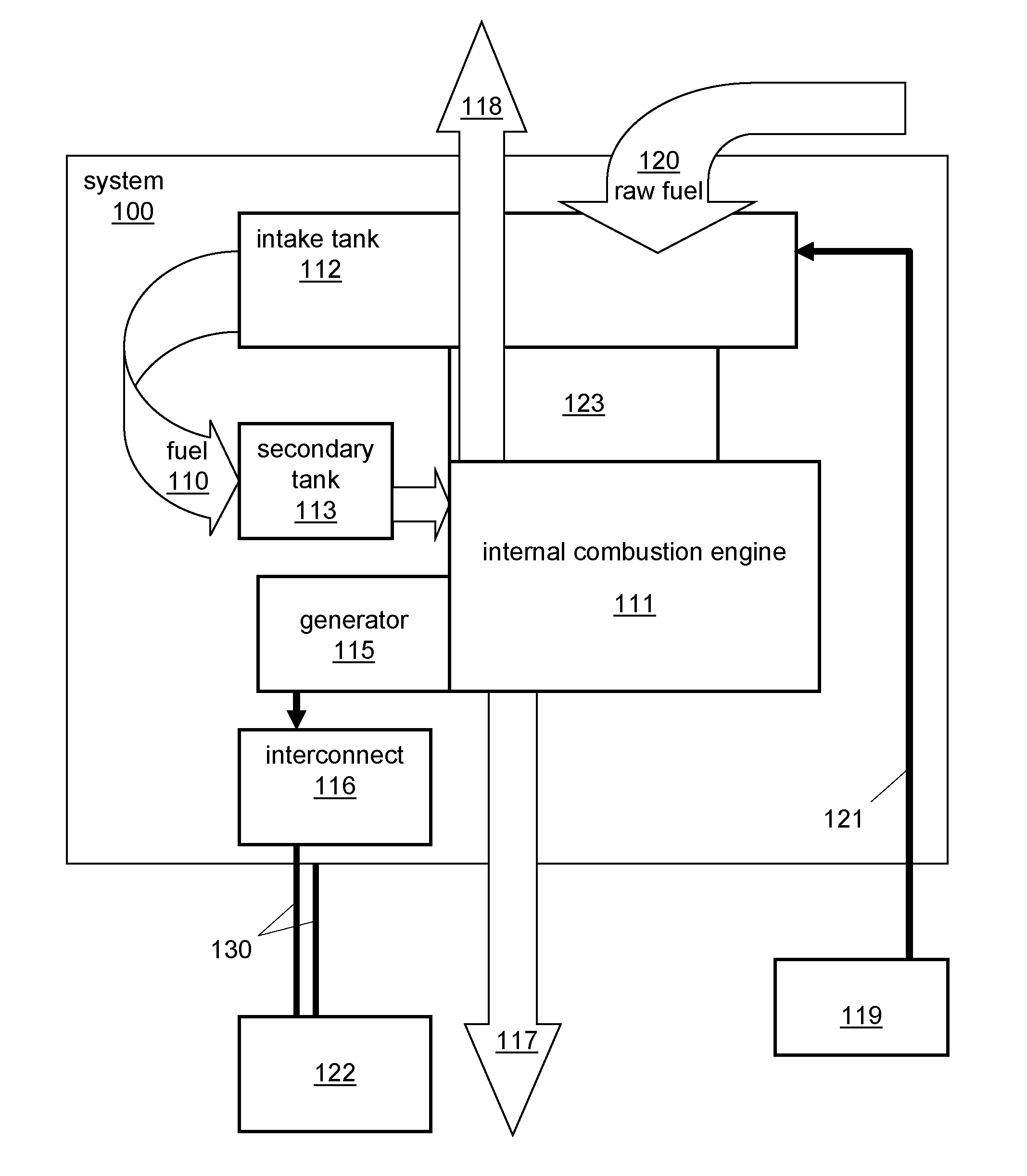
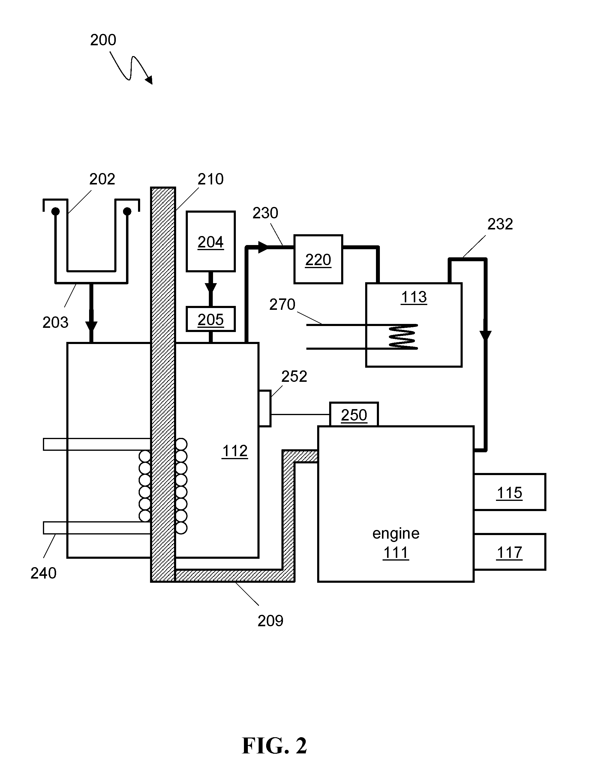
[0026]In overview and referring now to FIG. 1, in various embodiments, the waste-recovery cogeneration system 100 comprises a combined heat and power (CHP) system. In certain embodiments, the system 100 comprises a waste-recovered-fuel intake tank 112, a secondary tank 113, an internal combustion engine 111, a generator 115, and an electrical power interconnect device 116. In certain embodiments, an excess thermal energy system 117 is provided with the system 100. In various embodiments, an exhaust system 118 transports high-temperature combustion products from the system's engine 111. In certain embodiments, the cogeneration system 100 includes a transport line 121 and apparatus 119 for automated secondary fuel acquisition. In some embodiments, apparatus 119 comprises a grease interceptor, or grease trap. Raw fuel-laden waste 120 can be provided to intake tank 112. In certain embodiments, partly processed waste-recovered fuel 110 is provided to secondary tank 113 and...


PUM


Abstract

A waste-to-energy cogeneration system is described in various embodiments. The system can convert certain fuel-laden waste to thermal energy and electrical power. In certain embodiments, fuel-laden waste which has not been pre-filtered or pre-treated to remove particulates and water is deposited in the cogeneration system and prepared by the system for combustion in an unmodified diesel engine. The fuel-laden waste can comprise oils, greases and fats from food preparation which are contaminated with water and particulates. Thermal and mechanical energy produced by the engine are utilized to provide thermal energy and electrical power external to the cogeneration system.

Description

CROSS-REFERENCE TO RELATED U.S. APPLICATIONS[0001]The present application claims priority to U.S. provisional patent application No. 61 / 042,497 filed on Apr. 4, 2008, and to U.S. provisional patent application No. 61 / 042,488 filed on Apr. 4, 2008, both of which are incorporated herein by reference.FIELD OF THE INVENTION[0002]The invention relates to a system, apparatus and methods for recapturing energy from fuel-laden waste, e.g., used vegetable oil, grease, fat, wax, waste petroleum products, waste synthetic products. The invention more particularly pertains to cogeneration of heat and power from waste hydrocarbons.BACKGROUND[0003]There have been recent advances in waste-to-energy conversion systems. Some systems utilize municipal solid waste containing hydrocarbon products, and convert the waste to energy using a large-scale facility, e.g., in a building-size or multi-structure facility. In some cases, a municipal solid waste stream is obtained at little or no cost. The waste str...

Claims


Application Information

Patent Timeline
IPC IPC(8): F01K25/00F02B63/04F01N5/02F02M31/00
CPCC10L1/00Y02T10/36F23G7/05F23G2202/103F23G2202/70F23G2206/202F23G2206/203Y02E20/12Y02E20/14Y02T10/16F01K13/00F02M21/0215F02M31/16F02D19/0652F02D29/06Y02T10/126F23G2900/7002F23G5/46Y02T10/12Y02T10/30
Inventor PERET, JAMES EDWARD
Owner UNIV OF MIAMI
Why Eureka
Try Eureka