Controlled contactless power transmission

a power transmission system and control technology, applied in the direction of dc-ac conversion without reversal, instruments, nuclear engineering, etc., can solve the problems of series reaction between input and load, significant change in load voltage, and stronger change of load voltage, so as to increase the control capability of output power and reduce switching losses

Active Publication Date: 2011-02-17
SCHLEIFRING & APPBAU
View PDF12 Cites 31 Cited by
  • Summary
  • Abstract
  • Description
  • Claims
  • Application Information

AI Technical Summary

Benefits of technology

[0014]The disadvantages of the prior art may be overcome by a rotary joint designed for non-contacting inductive transmission of electrical power having a constant output voltage or current so that a feedb

Problems solved by technology

This results in a series reactance between input and load.
This leads to significant changes in load voltage.
Furthermore with a lower coupling factor changes of the load resistance result in stronger changes of load voltage.
One of the most serious problems in such resonance circuits is the energy stored in the resonance elements e.g. the inductance and the capacitance.
This energy makes a quick control or change of the output parameters (Voltage, Current) very difficult.
Another problem is that a data link is required for feedback of the measured output voltage to the primary side.
With rotary joints there is the problem that information from a sensor must be transmitted from the output side to the input side, i.e. between two units that are rot

Method used


Image

  • Controlled contactless power transmission
  • Controlled contactless power transmission
  • Controlled contactless power transmission

Examples


Embodiment Construction

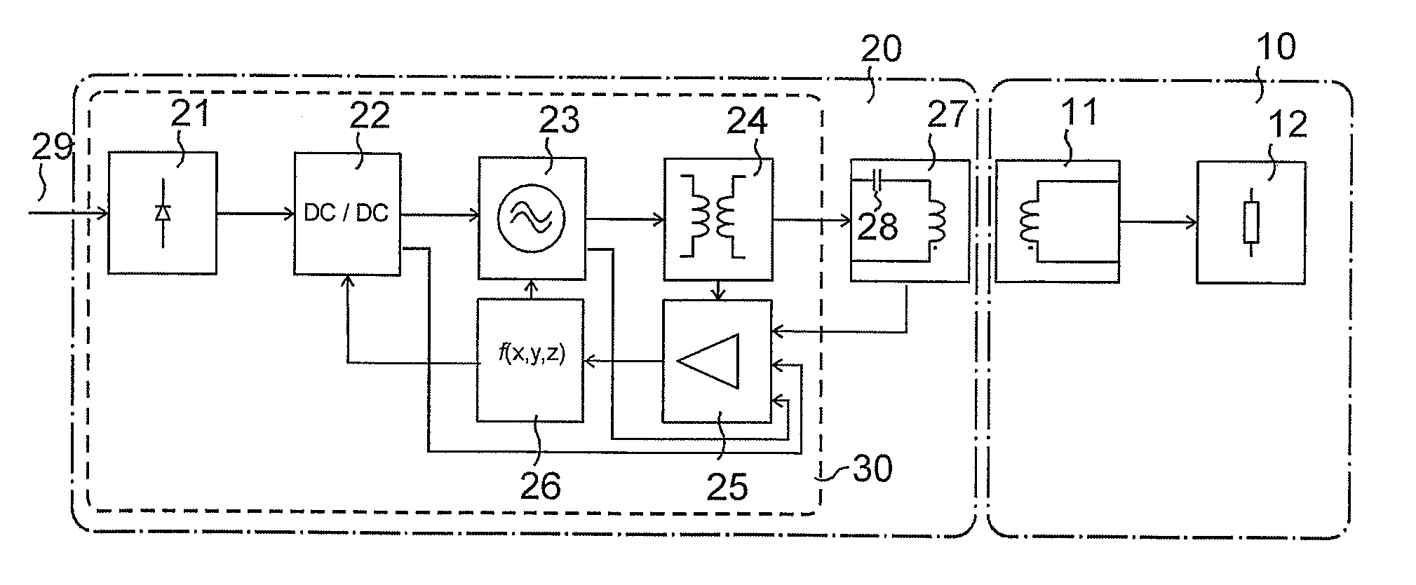
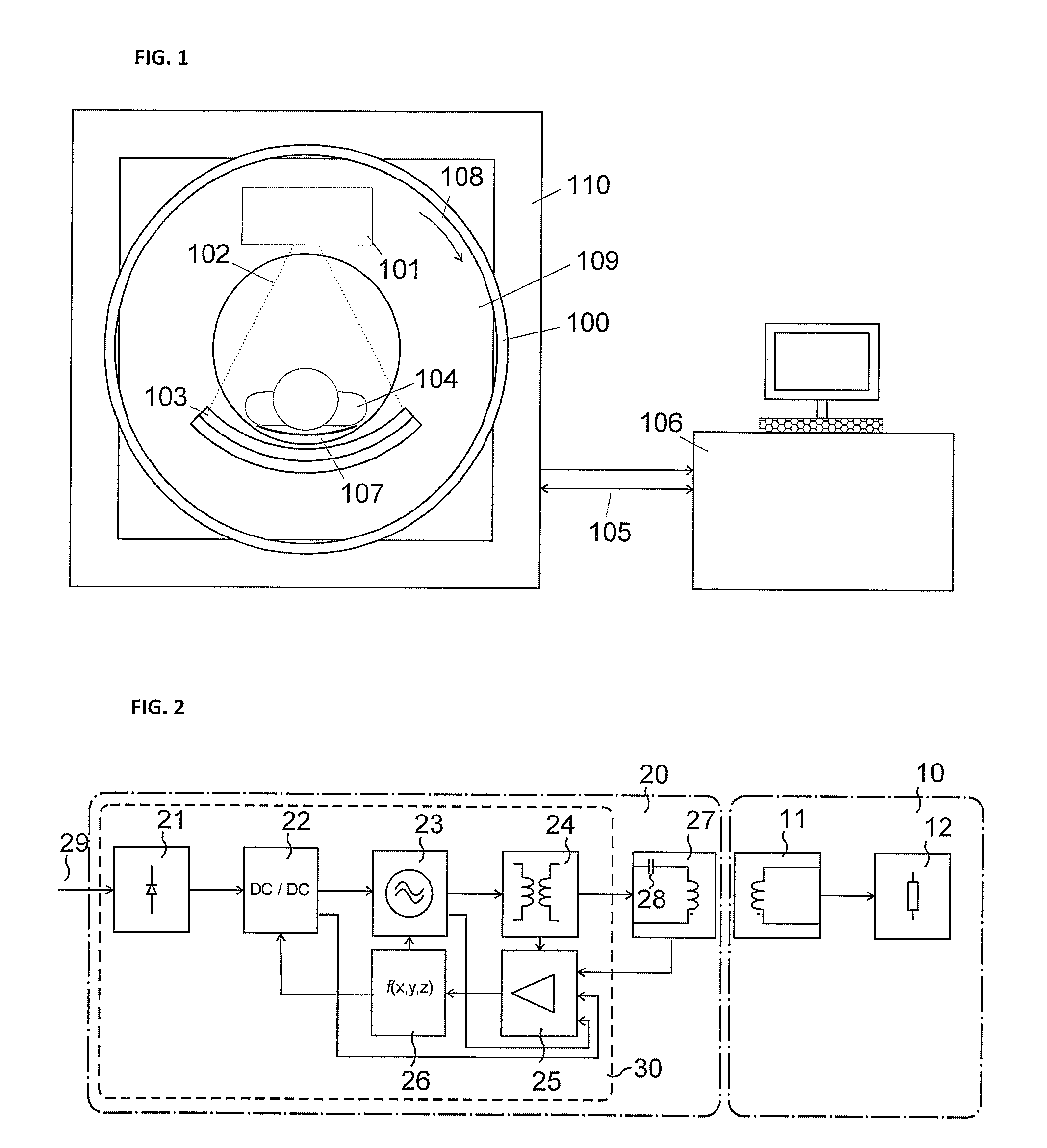
[0028]In a preferred embodiment output voltage and output current of the DC / DC converter 22 are measured to estimate voltage and current at the load 12. As an alternative input voltage and / or current thereof are measured. Specifically the output values of the DC / DC converter 22 are easy to measure as the output is a DC voltage and a corresponding DC current. By using these measured values new set point values for the DC / DC converter are calculated by the function generator 26.

[0029]In a further embodiment the matching transformer has a shield between primary and secondary windings. This further helps to reduce suppression of common mode currents. This shield may be a foil or a winding.

[0030]A further embodiment relates to the DC / DC converter 22. It preferably includes a cascaded control circuit, including a first high-speed current control loop and a second low speed voltage control loop defining the set point for the first control loop.

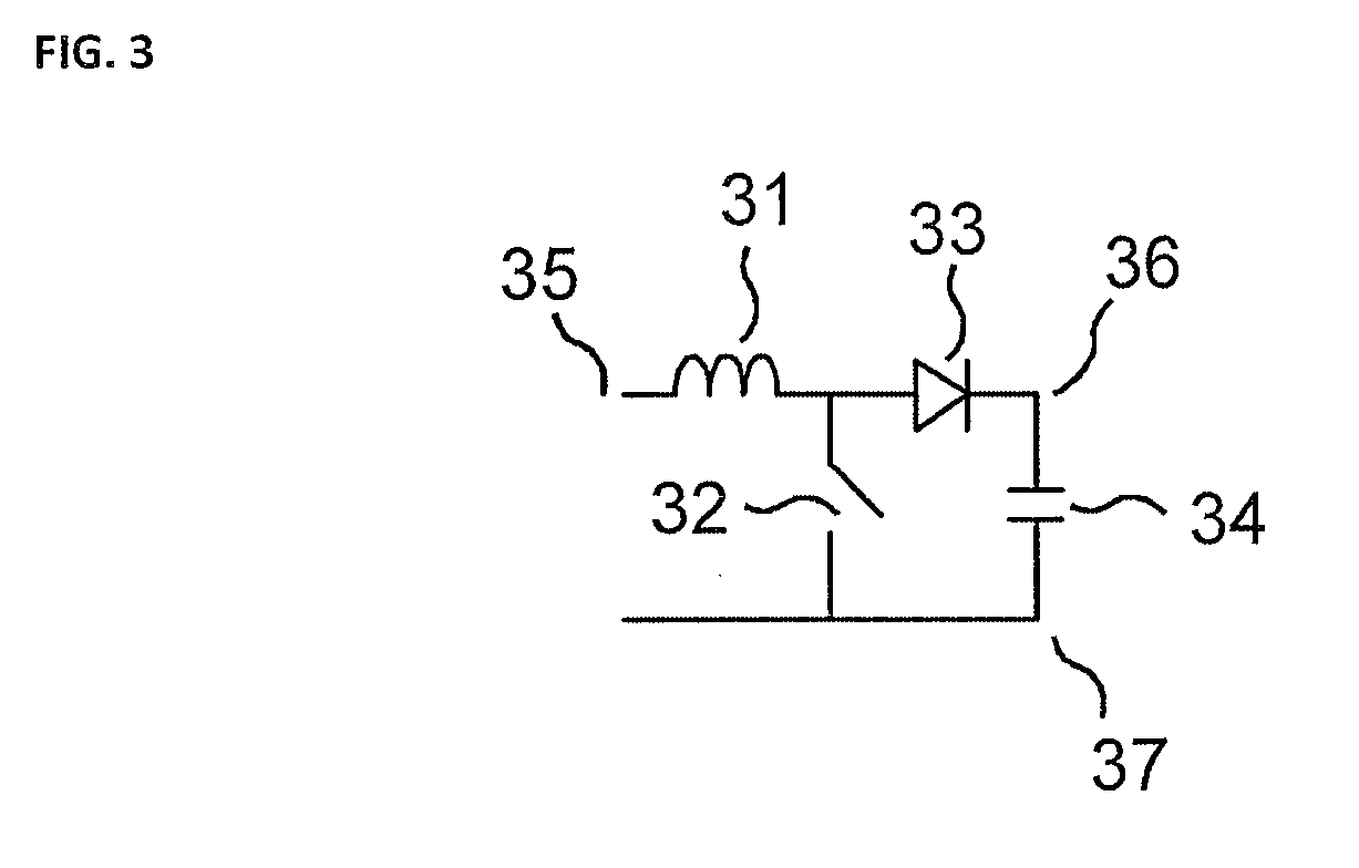
[0031]In another embodiment the DC / DC converte...


PUM


Abstract

An inductive coupled power transmission circuit has a rotating transformer, including an AC voltage supply for feeding an AC voltage via a series capacitor into the primary winding of said rotating transformer and a load being coupled to the secondary winding of said rotating transformer. The AC voltage supply includes a line rectifier for receiving AC voltage from a power line and generating a DC voltage. This is fed into a DC/DC converter for converting the DC voltage from the line rectifier into a controlled intermediate DC voltage. An AC generator generates an AC voltage from the intermediate DC voltage and feeds this via a matching transformer into the primary winding of the rotating transformer. A measuring circuit measures voltages and/or currents within the AC voltage supply and a function generator estimates voltage and/or current values at the load based on the measured values and controls the DC/DC converter and/or the AC generator based on the estimated values.

Description

BACKGROUND OF THE INVENTION[0001]1. Field of the Invention[0002]The invention relates to a contactless power transmission system for transmission of power between a rotating part and a stationary part, in particular between a rotating part and a stationary part of a computer tomograph, and also to a method for transmitting power via a rotating power transmission device.[0003]2. Description of the Relevant Art[0004]With rotating units such as radar units or also computer tomographs, and also with linearly movable units such as crane and conveyor units, it is necessary to transmit electrical power between units that are movable relative to each other.[0005]Non-contacting inductive rotary joints are an advantageous substitute for the known mechanical slip-rings for transmission of electrical energy. In inductive transmission technology a coupling between rotatable units is effected with magnetic fields without contact. This has an advantage over mechanical slip-rings in that torque, we...

Claims


Application Information

Patent Timeline
IPC IPC(8): H02M7/06
CPCA61B6/56H01F38/18H02J5/005Y02B70/126H02M5/48H02M7/64H05G1/10H02M1/4225Y02B70/10H02J50/70H02J50/12H02J2310/23
Inventor ZIMPFER, ARNO
Owner SCHLEIFRING & APPBAU
Why Eureka
Try Eureka