
Magneto-caloric regenerator system and method

Inactive Publication Date: 2011-03-03
GENERAL ELECTRIC CO
View PDF8 Cites 80 Cited by
  • Summary
  • Abstract
  • Description
  • Claims
  • Application Information

AI Technical Summary

Benefits of technology

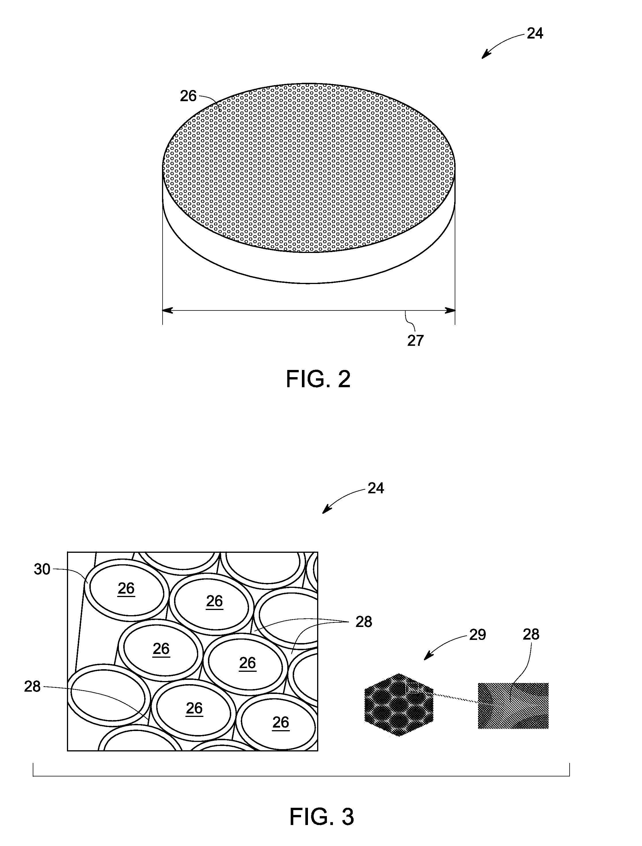
[0006]Briefly, a regenerator having a thermal diffusivity matrix is presented. The thermal diffusivity matrix includes magneto-caloric material having multiple miniature protrusions intimately packed to form a gap between the protrusions. A fluid path is provided within the gap to facilitate flow of a heat exchange fluid and further provide efficient thermal exchange between the heat exchange fluid and magneto-caloric material. A first layer is disposed on each of the miniature protrusion to physically isolate the heat exchange fluid and magneto-caloric material, wherein the first layer further includes a soft magnetic material configured to simultaneously enhance a permeability and a thermal efficiency of the thermal diffusivity matrix.
[0007]In another embodiment, a regenerator having a thermally conducting material is presented. The thermally conducting material defines multiple micro fluidic channels adjacent to each other. A magneto-caloric material is disposed within multiple pockets formed between the micro fluidic channels. A fluid path is defined within said micro fluidic channels. The fluid path facilitates flow of a heat exchange fluid, wherein the heat exchange fluid and magneto-caloric material are in thermal communication and physical isolation.
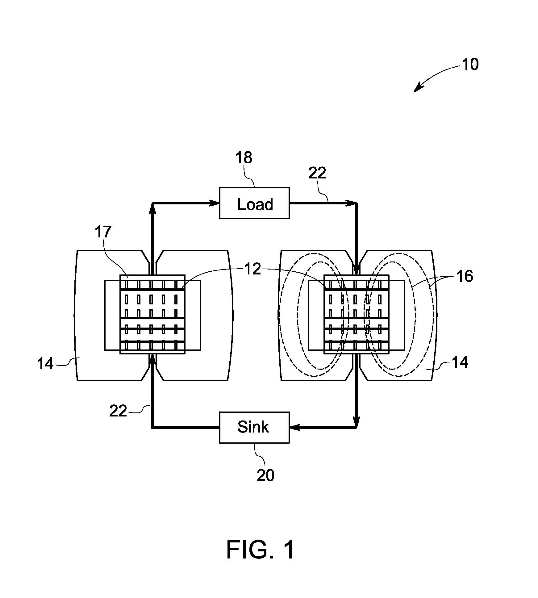
[0008]A magneto-caloric system having a regenerator, an excitation source, a magnetic core, and a thermal exchange cycle is presenter. The regenerator includes a magnetically aligned cluster of a magneto-caloric material, the cluster having miniature protrusions arranged intimately to form a gap between said each miniature protrusion. A fluid path is defined within the gap and configured to exchange thermal units between a heat exchange fluid and the magneto-caloric material. The excitation source is configured to generate magnetic flux to magnetize and de-magnetize the regenerator cyclically. The magnetic core is configured to channalize magnetic flux throught the regenerator. The thermal exchange cycle is coupled a load, a sink, and the regenerator. The heat exchange fluid facilitates exchange of thermal units between the load and the sink.

Problems solved by technology

However, such gas compression technology has some drawbacks.
First, a Hydro-fluorocarbon (HFC), Hydro-chlorofluorocarbon (HCFC), or chlorofluorocarbon (CFC) gas, a typical refrigerant working material used most commonly in this technology, may pose some level of environmental challenges if not disposed of properly.
Additionally, the gas compression technology is a mature technology and extracting additional energy savings out of this technology has proved difficult.
Magneto-caloric materials include multiple alloys that are typically brittle and have a tendency to become powders due to inherent stress in the material.
Furthermore, magneto-caloric materials have low thermal conductivity and hence are less efficient when subjected to transient operating cycle due to cyclic magnetization and demagnetization.
Further, several magneto-caloric material when directly exposed to the aqueous (water based) heat exchange fluids reacts to form oxide or hydroxide layer, which in turn lower the efficiency and reliability of the heat exchanger in magneto-caloric refrigeration systems.

Method used


Image

  • Magneto-caloric regenerator system and method
  • Magneto-caloric regenerator system and method
  • Magneto-caloric regenerator system and method

Examples


Embodiment Construction

[0020]Typically, the magnetic-caloric system is based on the active magnetic regenerative (AMR) cycle. The AMR cycle implements magneto-caloric materials based heat exchangers often referred as regenerators for heat transfer between magneto-caloric material and a heat exchange fluid. Multiple layers of magneto-caloric material with different Curie temperature are used to achieve the temperature span. Regenerators would also include insulating layers between the stages to help maintain the thermal losses and hence the temperature gradient across regenerators. Embodiments disclosed herein, describes various aspects to design and fabrication of regenerators and magneto-caloric systems.

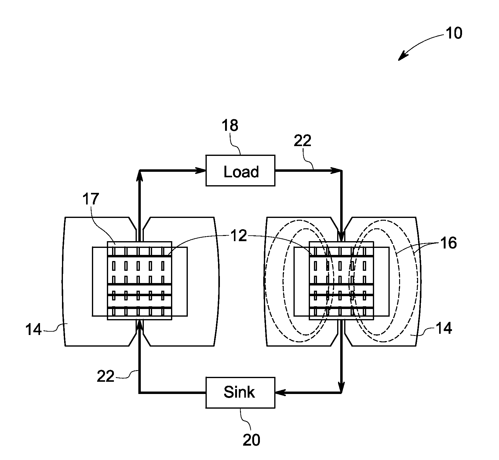
[0021]Referring now to the drawings, FIG. 1 illustrates an exemplary magneto-caloric refrigeration system 10 that is configured to provide cooling using the magneto-caloric effect. The system 10 includes a regenerator 17 having multiple magneto-caloric elements coupled thermally (represented by reference ...


PUM


Abstract

A regenerator having a thermal diffusivity matrix is presented. The thermal diffusivity matrix includes magneto-caloric material having multiple miniature protrusions intimately packed to form a gap between the protrusions. A fluid path is provided within the gap to facilitate flow of a heat exchange fluid and further provide efficient thermal exchange between the heat exchange fluid and magneto-caloric material. A first layer is disposed on each of the miniature protrusion to physically isolate the heat exchange fluid and magneto-caloric material, wherein the first layer further includes a soft magnetic material configured to simultaneously enhance a permeability and a thermal efficiency of the thermal diffusivity matrix.

Description

BACKGROUND[0001]The subject matter disclosed herein generally relates to magneto-caloric refrigeration and in particular to regenerators in magneto-caloric refrigeration.[0002]Conventional refrigeration technology has often utilized the adiabatic expansion or the Joule-Thomson effect of a gas. However, such gas compression technology has some drawbacks. First, a Hydro-fluorocarbon (HFC), Hydro-chlorofluorocarbon (HCFC), or chlorofluorocarbon (CFC) gas, a typical refrigerant working material used most commonly in this technology, may pose some level of environmental challenges if not disposed of properly. Additionally, the gas compression technology is a mature technology and extracting additional energy savings out of this technology has proved difficult.[0003]An alternative refrigeration technique involves a method that takes advantage of entropy change accompanied by a magnetic or magneto-structural phase transition of a magneto-caloric material, referred to as a magnetic phase tr...

Claims


Application Information

Patent Timeline
IPC IPC(8): F25B21/00
CPCF25B21/00Y02B30/66F25B2321/002Y02B30/00
Inventor BARVE, JAYESHKUMAR JAYANARAYANSAMIAPPAN, CHANDRASEKHARREDDY, SUDHAKAR EDDULAJOHNSON, FRANCISSAHA, ATANUKRISHNA, KALAGA MURALICHANDRAN, MAHESH
Owner GENERAL ELECTRIC CO
Learn More