
Electrode structure and electric energy storage device

a technology of electric energy storage and electrode structure, which is applied in the direction of non-aqueous electrolyte accumulator electrodes, cell components, electrical apparatuses, etc., can solve the problems of easy deterioration of charge/discharge efficiency, increase in particle size, and reduced capacity, so as to improve the repetitive charge/discharge efficiency, the effect of reducing the damage caused by the expansion and shrinkage of active material particles

Inactive Publication Date: 2011-03-03
CANON KK
View PDF5 Cites 45 Cited by
  • Summary
  • Abstract
  • Description
  • Claims
  • Application Information

AI Technical Summary

Benefits of technology

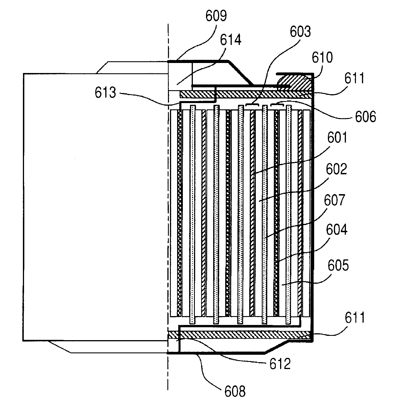
[0014]The present invention can provide an electrode structure which has a high power density and is superior in repetitive charge / discharge efficiency, and an electric energy storage device using the electrode structure.
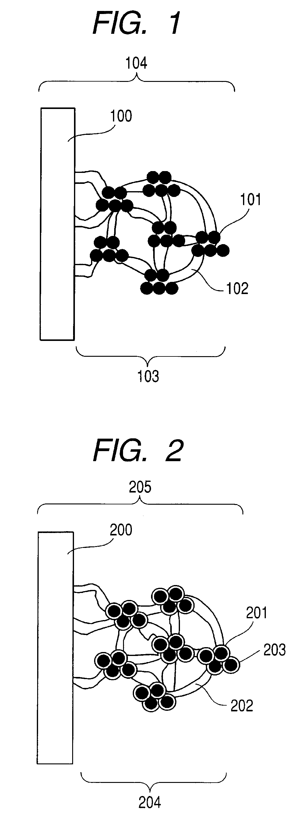
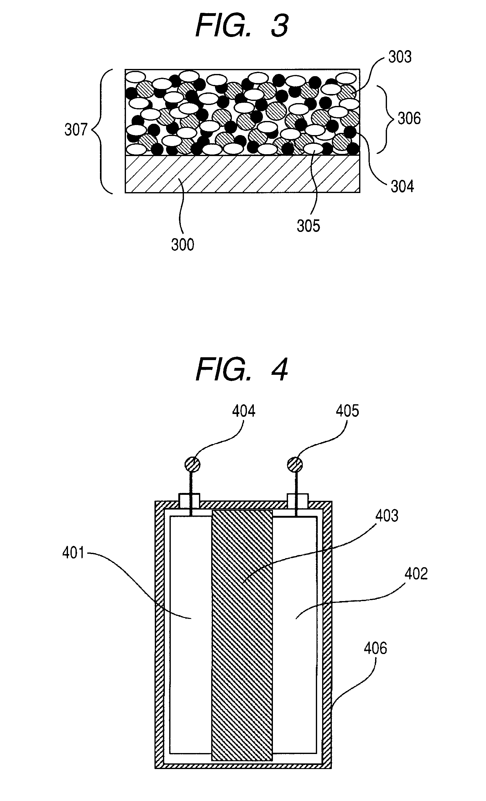
[0015]According to the present invention, in particular, the mechanical properties and heat treating temperature of the binder as a structural element of the electrode structure are defined, and the breakage of the electrode caused by the expansion and shrinkage of the active material particles can be reduced within the defined range. As a result, the electric energy storage device using the electrode structure of the present invention can limit the increase in internal resistance caused by the repetition of charge / discharge operations, thereby the repetitive charge / discharge efficiency can be improved. This effect is significant especially when the particle size of the active material particle is reduced to improve the power density.
[0016]Further features of the present invention will become apparent from the following description of exemplary embodiments with reference to the attached drawings.

Problems solved by technology

According to the technologies described in Patent Literature 1, since the thermal history temperature is high and therefore, the growth of crystals of silicon or tin is accelerated with the result that an increase in a particle size, a reduction in capacity caused by the increased particle size and a deterioration of charge / discharge efficiency are easily caused.
Also, at high thermal history temperature, oxidation of oxygen and water stuck to the crystals is easily caused during the course of the process, with the result that the amount of an oxide of silicon or tin to be produced is increased, leading to a fast deterioration in charge / discharge efficiency.

Method used


Image

  • Electrode structure and electric energy storage device
  • Electrode structure and electric energy storage device
  • Electrode structure and electric energy storage device

Examples


examples

[0161]The present invention will be explained in more detail in examples.

[0162]Production of a negative electrode structure of the electric energy storage device

[0163]Examples of the production of the negative electrode structure of the electric energy storage device will be given below.

[0164]100 parts by weight of a silicon powder having an average particle size of 0.14 μm which was obtained by milling metal silicon (purity: 99%) by using a wet beads mill, 70 parts by weight of artificial graphite having an average particle size of 5 μm, and 3 parts by weight of acetylene black were mixed at 300 rpm for 20 min in a planetary ball mill using agate balls. Then, 132 parts by weight of a N-methyl-2-pyrrolidone solution containing 15% by weight (on solid basis) of each of the binders A1 to A8 and B1 to B3 as shown in Table 1 and 130 parts by weight of N-methyl-2-pyrrolidone were added to the obtained mixture, which was then mixed at 300 rpm for 10 min by a planetary ball mill to prepare...

example 9

[0185]Next, a different embodiment according to the present invention, that is, an example showing the effect according to the content of the binder will be shown.

1. Production of a Negative Electrode

[0186](1) Preparation of a Negative Electrode Active Material

[0187]A high-frequency (RF) induction coupling heat plasma generator which was constituted of a reactor with which a heat plasma torch and a vacuum pump were connected was used. First, the reactor was vacuumized by a vacuum pump, 200 l / min of argon gas and 10 l / min of hydrogen gas were made to flow as the plasma gas. Pressure in the reactor was controlled to 50 kPa and 80 kW electric power with 4 kHz high frequency RF electric field was applied to the inductive coil to generate a plasma. Then, a powder raw material prepared by blending 90 parts by weight of a silicon powder having an average particle size of 4 μm with 10 parts by weight of metal aluminum having an average particle size of 1 μm was supplied to the inside of a h...

example 10

[0194]Next, an example of a production of an electric energy storage device is shown below.

[0195](1) Preparation of a Negative Electrode Active Material

[0196]A high-frequency (RF) inductively coupled heat plasma generator which was constituted of a reactor with which a heat plasma torch and a vacuum pump were connected was used. First, the reactor was vacuumized by a vacuum pump, 200 l / min of argon gas and 10 l / min of hydrogen gas were made to flow as the plasma gas. Pressure in the reactor was controlled to 50 kPa, and 80 kW electric power with 4 kHz frequency electric field was applied to the inductive coil to generate a plasma. Then, a powder raw material prepared by blending 90 parts by weight of a silicon powder having an average particle size of 4 μm with 10 parts by weight of metal aluminum having an average particle size of 1 μm was supplied to inside of the heat plasma at a feed rate of about 500 g / hr by using 15 l / min argon gas as the carrier gas, to thereby obtain a micro...


PUM


Abstract

Provided is an electrode structure having a high power density and being superior in repetitive charge / discharge efficiency and an electric energy storage device using the electrode structure. The electrode structure includes an electrode material layer including an electrode material including active material particles containing at least one of silicon, tin and alloys containing at least one of them, and a binder binding the active material particles, the binder has the following characteristics: tensile modulus: 2000 MPa or more, breaking strength: 100 MPa or more, break elongation: 20% to 120% and the ratio of breaking strength / break elongation >1.4 (MPa / %), and an average particle size of the particles is 0.5 μm or less, the electrode structure has a maximum thermal history temperature less than 350° C. and lower than the glass transition temperature of the binder. The electric energy storage device uses, as its negative electrode, the electrode structure.

Description

CROSS-REFERENCE TO RELATED APPLICATIONS[0001]This application is a continuation of International Application No. PCT / JP2010 / 004126, filed Jun. 21, 2010, which claims the benefit of Japanese Patent Application No. 2009-149192, filed Jun. 23, 2009.BACKGROUND OF THE INVENTION[0002]1. Field of the Invention[0003]The present invention relates to an electrode structure which has a high power density, is superior in repetitive charge / discharge efficiency and can store and emit lithium ions. The present invention also relates to an electric energy storage device provided with the electrode structure.[0004]2. Description of the Related Art[0005]An electric energy storage device that has a high power density and that is superior in repetitive charge / discharge efficiency has long been demanded.[0006]A lithium secondary battery utilizing silicon, tin or their alloys as an active material for an electrode structure of its negative electrode has, in spite of its high power density, the problem th...

Claims


Application Information

Patent Timeline
IPC IPC(8): H01M4/40H01M4/58H01M4/62H01M4/48H01G11/24H01G11/28H01G11/38H01G11/46
CPCH01G11/38H01G11/46H01M4/134H01M4/38Y02E60/13H01M10/052Y02E60/122H01G11/24H01G11/28H01M4/621H01M4/386H01M4/387Y02E60/10
Inventor KASHIWAZAKI, AKIOKAWAKAMI, SOICHIRO
Owner CANON KK
Learn More