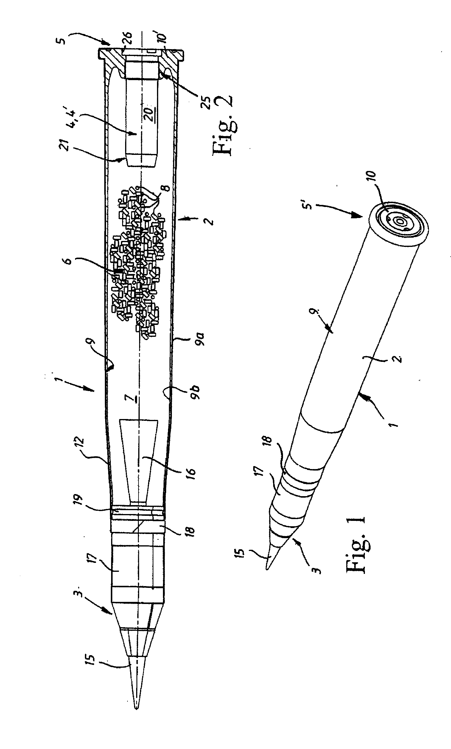
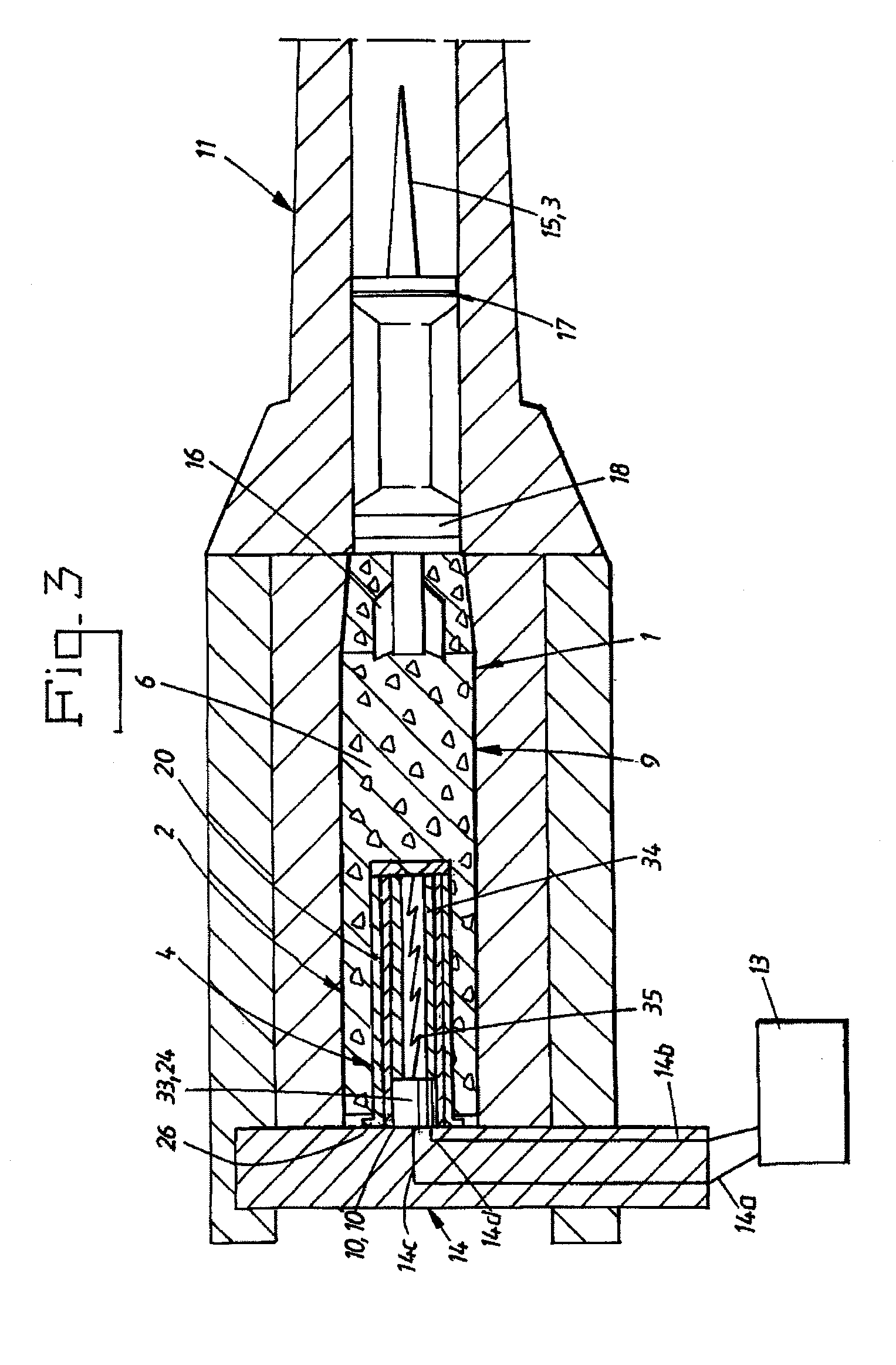
Plasma generator for an electrothermal-chemical weapons system comprising ceramic, method of fixing the ceramic in the plasma generator and ammunition round comprising such a plasma generator

Inactive Publication Date: 2011-03-10
BAE SYST BOFORS
View PDF8 Cites 11 Cited by
  • Summary
  • Abstract
  • Description
  • Claims
  • Application Information

AI Technical Summary

Benefits of technology

[0065]The inevitably high plasma temperatures in the plasma generator make it necessary to protect the combustion chamber channel walls by introducing a highly heat-resistant ceramic insert or using such a material to line the combustion chamber channel walls. The ceramic is moreover significantly more impervious than a glass fiber insulation, for example, since glass fiber insulation allows the current to pass more readily through the space between the glass fiber threads.
[0066]Shrink-fixing the ceramic inside the combustion chamber channel according to the invention, so that the play, which would otherwise be formed between the ceramic and the walls of the combustion chamber channels by material irregularities and tolerance defects, is eliminated or at least greatly reduced, and so that the shrink-fixing causes the ceramic insert/inner lining/tube to be compressively pre-stressed by the contraction of the enclosing combustion chamber as it shrinks, to such a degree that the tensile stresses later occurring in the ceramic during the plasma formation are less than the compressive pre-stressing or are counteracted to such a degree that the resulting stresses in the ceramic are lower than the maximum permitted tensile stresses for the ceramic, is a satisfactory way of solving the problem of the ceramic readily braking apart under the very high tensile stresses that would otherwise occur in the c

Problems solved by technology

The increase in velocity which is thereby feasible is nevertheless relatively limited.
One reason for the limited increase in velocity is that an extra quantity of propellant charge supplied, including the propellant gases formed thereby, also has to be accelerated together with the projectile, so that a proportion of the energy from the extra quantity of propellant charge supplied is needed for this purpose, whilst all the propellant charge that is unburned when the projectile leaves the barrel does not provide any increase in velocity, since the gas excess pressure falls to the ambient atmospheric pressure as soon as the projectile leaves the barrel.
It can also be a problem to fill conventional ammunition rounds with all the quantity of propellant charge that is required in order to achieve the desired muzzle velocity, and at the same time to find space for the actual projectile without greatly increasing the total weight of the ammunition round.
Despite the aforementioned efforts to improve the current, conventional methods of propulsion and the propellant charges used for this purpose, however, the practically feasible upper limit for the muzzle velocity in conventional barreled weapons, and also for the chemically progressive, inhibited and perforated propellants has been reached at approximately 1500-1800 m/s.
This is due to the fact that the chemical progressivity of the currently known propellant charges has an upper limit, and because at present the multiple perforation of the constituent propellant charges cannot be performed with just the requisite fine distribution.
Furthermore these measures, including said inhibition, are not all that easy to calculate and implement in advance, so that the desired pressure curve is always exactly the same every time for each type of propellant charge fired.
It will be appreciated that there is a negative effect on the firing accuracy of the projectile if the muzzle velocity cannot always be determined beforehand for each round fired.
The ‘piccolo’ normally lacks an end orifice opening, so that compared to the plasma jet burner, it is not possible to generate the same powerful plasma jet directed forwards in the longitudinal direction of the plasma jet burner.
Owing to the very high temperature and also the very high internal pressure inside the plasma generator, the combustion chamber of the plasma generator and also the barrel will be exposed to very great thermal and load stresses.
The ceramics characteristically have a relatively good compressive strength but otherwise have a low strength.
In the aforementioned plasma jet burner in U.S. Pat. No. 4,957,035, these tensile stresses would easily tear the ceramic apart and cause serious leakage of heat, current, voltage and/or plasma, resulting in inevitable damage to the weapon, if the strength of the plasma jet burner were no

Method used


Image

  • Plasma generator for an electrothermal-chemical weapons system comprising ceramic, method of fixing the ceramic in the plasma generator and ammunition round comprising such a plasma generator
  • Plasma generator for an electrothermal-chemical weapons system comprising ceramic, method of fixing the ceramic in the plasma generator and ammunition round comprising such a plasma generator
  • Plasma generator for an electrothermal-chemical weapons system comprising ceramic, method of fixing the ceramic in the plasma generator and ammunition round comprising such a plasma generator

Examples


second embodiment

[0114]In the second embodiment shown in FIG. 9 with the unique design of the central contact device 33′ and the flange 26′, comprising the so-called laminated contacts 42′, 45′ with the laminated contact strips 42, 45 fitted in the groove 41 and the inner surface 44′ of the rear central cavity 44, it is possible to automatically fire several ammunition rounds 1 in succession and also to fire several pulses for each such ammunition round 1, without play and the resulting arc occurring between the contact devices 48, 49 and laminated contacts 42′, 45′ of the breech 14 and the plasma generator 4′, such arcs normally exposing the contact devices 48, 49 to the risk of fusing tightly together, since the laminated contacts 42′, 45′ interacting with the contact devices 48, 49 readily cope with normal external vibrations, recoil and the other vibrations that occur, in the barreled weapon in question when the plasma generator 4′ is used.

first embodiment

[0115]One difference in the design of the laminated contacts 42′, 45′ shown in FIG. 9 compared to the first embodiment shown in FIG. 4 is that the laminated contact strips 42, 45 in FIG. 9 allow the contact devices 48, 49 and the laminated contact strips 42, 45 scope to slide a certain axial distance relative to one another and to still be in firm contact, thanks to the slide surface on each part interacting between them. This design of the contact surface naturally produces a larger contact surface than in the usual spot or surface contact type, so that the current transmission is distributed over this larger contact surface, thereby facilitating the current transmission and eliminating the risk of arcing, which prevents fusing / burning together even under several pulses.

[0116]Functional Description

[0117]The manufacture, function and use of the plasma generator 4, 4′ according to the invention are as follows. Compare FIG. 3 and FIG. 4 for the aforementioned first embodiment with FIG...


PUM

PropertyMeasurementUnit
Temperatureaaaaaaaaaa
Pressureaaaaaaaaaa
Molar massaaaaaaaaaa

Abstract

The invention relates to a plasma generator (4) for electrothermal and electrothermal-chemical weapons systems, the plasma generator being intended, via at least one emitted energy pulse, to form a plasma, which is designed to accelerate a projectile (3) along the barrel (11) of the weapons system in question, the plasma generator comprising a combustion chamber (20) having an axial combustion chamber channel (20′) and a ceramic arranged inside the combustion chamber channel for insulating the combustion chamber. According to the invention the ceramic consists of a shrink- fixed, compressively pre-stressed ceramic tube (23). The invention also relates to a method for shrink-fixing the ceramic tube in the combustion chamber channel as well as an ammunition round comprising a plasma generator according to the invention.

Description

FIELD OF THE INVENTION [0001]The present invention relates to a plasma generator for electrothermal and electrothermal-chemical weapons systems, the plasma generator being intended, via at least one emitted energy pulse, to form a plasma, which is designed to accelerate a projectile along the barrel of the weapons system in question, the plasma generator comprising a combustion chamber having an axial combustion chamber channel and a ceramic arranged inside the combustion chamber channel for insulating the combustion chamber.[0002]The present invention also relates to a method of fixing a ceramic in a plasma generator for electro-thermal and electrothermal-chemical weapons systems, the plasma generator being intended, via at least one emitted energy pulse, to form a plasma, which accelerates a projectile along the barrel of the weapons system in question, the plasma generator comprising a combustion chamber having an axial combustion chamber channel and a ceramic arranged inside the...

Claims


Application Information

Patent Timeline
IPC IPC(8): F42B5/02B23P11/02
CPCF42B5/08Y10T29/49865F42C19/12F42B3/14
Inventor GUSTAVSSON, LENNARTSTARK, OLA
Owner BAE SYST BOFORS
Why Eureka
Try Eureka