Lacrimal filler

a technology of filler and lacrimal vein, which is applied in the field of lacrimal outflow system filler mechanism, can solve the problems of eye discomfort, insufficient moisture supply to the eye, and des can become so severe, and achieve the effect of preventing the erosion of the canaliculus lining

Active Publication Date: 2011-03-17
FEZZA FAMILY PROPERTIES
View PDF15 Cites 10 Cited by
  • Summary
  • Abstract
  • Description
  • Claims
  • Application Information

AI Technical Summary

Benefits of technology

[0050]In accordance with the present invention there is provided an apparatus for treating dry eyes that includes a biomaterial mass inserted into a canaliculus in the lacrimal outflow system having an outer cross section less than the inner cross section of the canaliculus. The biomaterial mass absorbs liquid within the canaliculus to swell to form a lacrimal filler to seal the canaliculus at least partially. The lacrimal filler has an external cross section conforming to the internal cross section of the canaliculus and a soft outer surface relative to the surrounding tissues to prevent erosion of the canaliculus lining. The lacrimal filler forms an occlusion to prevent the outflow of liquid through the lacrimal outflow system to retain tears within the eye to maintain eye lubrication and wetness.

Problems solved by technology

The absence of any one of these components causes discomfort in the eye.
Dry eyes can be associated with the dysfunction of the lacrimal gland that causes it to supply insufficient moisture to the eyes.
DES can become so severe that corneal decomposition, ulceration and permanent visual loss can ensue.
While these treatments may provide temporary relief to DES, these treatments are ineffective against many forms of DES.
DES has a variety of causes but in general insufficient tears are produced to maintain an adequate aqueous layer.
Since it is not possible to increase lacrimal gland flow or turn the faucet higher, practitioners rely on adding moisture or blocking the outflow of tears away from the eye to create a wetter ocular environment.
Although artificial tears bring temporary relief, the manufactured solutions do not have the same composition as natural tears, so that the artificial tears are not as beneficial as a person's own tears.
One disadvantage of artificial tears is the increased risk of allergies to preservatives within the artificial tears.
Another disadvantage of artificial tears is that the relief tends to be short-lived.
As a result, the treatment must be re-administered several times each hour, which is usually not practical.
The risk of DES also increases with increasing age.
The application of drops by elderly patients can be challenging due to decreased dexterity, which represents another disadvantage of this approach.
Although these methods can provide an acceptable decrease in tear drainage, these methods may be difficult, painful, or irreversible without reconstructive surgery.
Sealing the tear ducts with cautery is painful and can be invasive and, potentially, irreversible.
Since it is sometimes difficult to determine whether in a particular patient the drainage is too great or the tear production is too small, irreversible blockage is not desirable.
A major problem with silicone plugs is that such plugs utilize a cap to hold the plug in place.
The cap may rub on the surface of the eye and irritate it.
As a result, obtaining the correct size plug can present a problem.
Another problem with silicone capped plugs is that they can become dislodged or lost.
The placement of such tiny plugs also presents a challenge.
The hardened intracanalicular plug can erode in the soft inner wall of the canallculus, which causes granulation tissue and infection.
However, such plugs only last for about one week.

Method used


Image

  • Lacrimal filler
  • Lacrimal filler
  • Lacrimal filler

Examples


Embodiment Construction

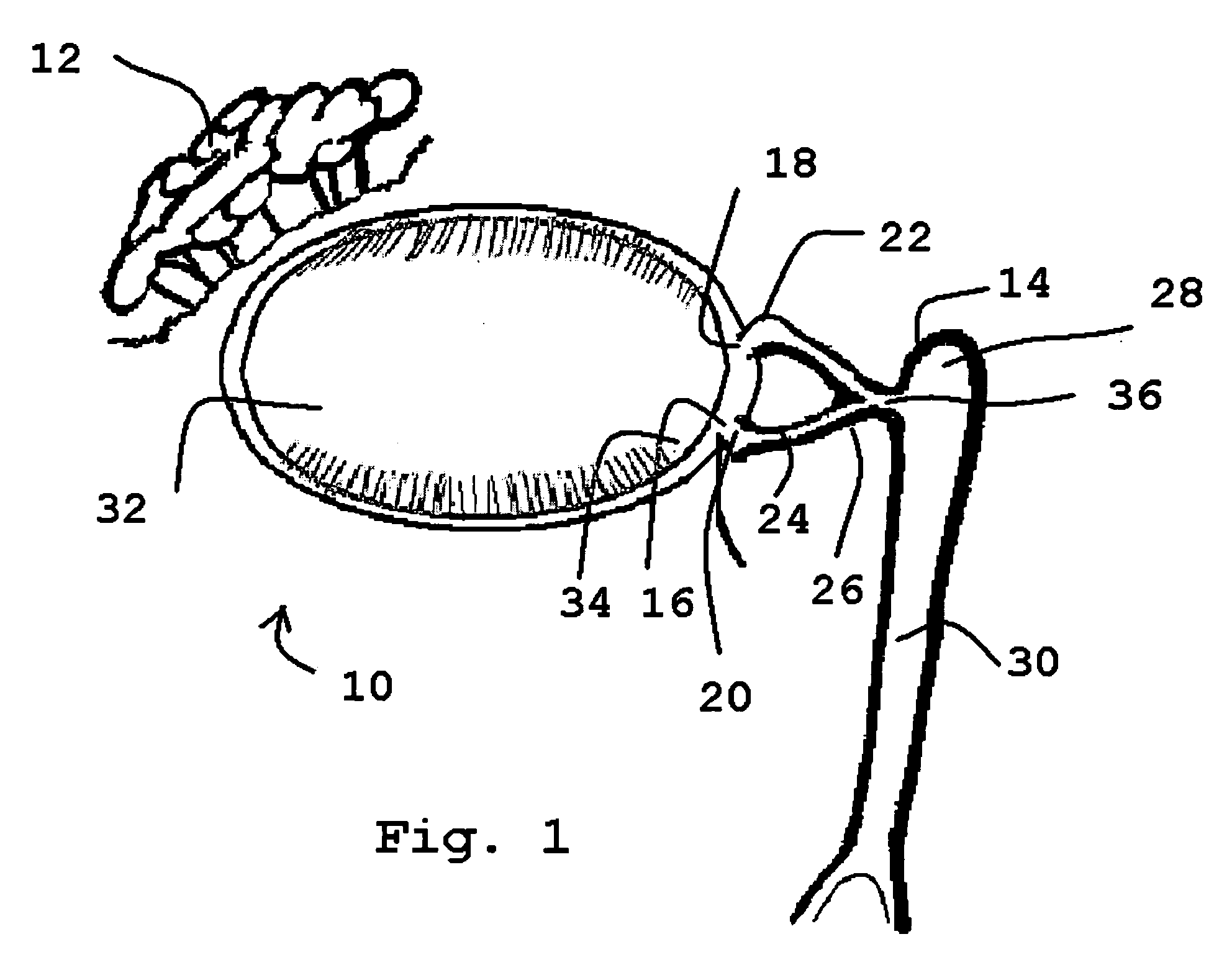
[0075]Referring to the drawings and, particularly, to FIG. 1, there is illustrated the human lacrimal system generally designated by the numeral 10. The lacrimal system 10 is divided into the secretory component or the lacrimal gland 12 and the excretory components that make up the lacrimal outflow system 14. The lacrimal outflow system 14 includes the puncta 16 and 18, the ampulla 20, the upper canaliculus 22, the lower canaliculus 24, common canaliculus 26, lacrimal sac 28, and nasolacrimal duct 30.

[0076]The eye 32 is positioned between the lacrimal gland 12 and the lacrimal outflow system 14. The eye 32 includes the medial canthal area 34. Tears pool within the medial canthal area 34 and enter the puncta 16, 18 to be eliminated through the lacrimal sac 28 into the nose (not shown).

[0077]The puncta 16, 18 are small orifices on the upper and lower lid margins, measuring 0.5-1.5 mm in diameter. The vertical ampulla 20 is typically 2 mm in length.

[0078]The canaliculi 22, 24 are essen...


PUM

PropertyMeasurementUnit
concentrationaaaaaaaaaa

Abstract

A biomaterial mass is inserted through a punctum into a canaliculus in the lacrimal outflow system with a syringe. The mass has an outer cross section that is less than the inner cross section of the canaliculus. The mass absorbs liquid to swell to form a lacrimal filler or sealing mechanism. The lacrimal filler has an external cross section that conforms to the internal cross section of the canaliculus and a soft outer surface relative to the surrounding tissues to prevent erosion of the canaliculus lining. The lacrimal filler forms an occlusion that prevents the outflow of liquid through the lacrimal outflow system to retain tears within the eye to maintain eye lubrication and wetness. The mass and syringe are provided in kit with a rubber stopper and, optionally, a punctal dilator, an injecting catheter, and an enzyme for dissolving or degrading the lacrimal filler at a later time.

Description

BACKGROUND OF THE INVENTION[0001]1. Field of the Invention[0002]This invention relates to a lacrimal outflow system filler mechanism and, more particularly, to an apparatus, kit, and method for treating dry eyes by creating an occlusion in the lacrimal outflow system.[0003]2. Description of the Related Art[0004]Human tears include three basic components: (1) lipids; (2) an aqueous component; and (3) mucin. The absence of any one of these components causes discomfort in the eye. While tears are eliminated through various methods in the human eye, tear evaporation accounts for 20% or more of tear elimination within the tear film in adults.[0005]A proper tear film is essential for maintaining eye health. Our eyes require moisture to wet and smooth the ocular surface to provide clear vision. Lacrimal secretions from the tear gland also protect the eye by washing away hazardous materials as well as providing important enzymes to fight infections. The pH for the tear film is maintained be...

Claims


Application Information

Patent Timeline
Patent Type & Authority Applications(United States)
IPC IPC(8): A61F9/007
CPCA61B17/12022A61B17/12099A61B17/12186A61K47/36A61B2017/1205A61F9/00772A61K9/0048A61B17/1219A61L24/0015A61L24/08A61L2400/06
Inventor FEZZA, JOHN
Owner FEZZA FAMILY PROPERTIES
Why Eureka
Try Eureka