System and method for regenerating a particulate filter accompanied by a catalyst

a technology of particulate filter and catalyst, which is applied in the direction of electric control, machines/engines, mechanical equipment, etc., can solve the problems of reducing engine efficiency, generating soot at higher engine speed and load conditions, and accumulating a large amount, so as to improve engine power and efficiency, reduce cylinder charge temperature, and improve efficiency

Active Publication Date: 2011-03-31
FORD GLOBAL TECH LLC
View PDF21 Cites 38 Cited by
  • Summary
  • Abstract
  • Description
  • Claims
  • Application Information

AI Technical Summary

Benefits of technology

[0003]Direct injection gasoline engines offer improved efficiency because fuel injected directly into a cylinder can reduce cylinder charge temperature. As a result, additional air may enter a cylinder as compared to an equivalent cylinder that has port injected fuel. Consequently, engine power and efficiency may be improved. In addition, direct injection gasoline engines may exhibit improved transient fuel control because there is less tendency for fuel to collect at a cylinder intake port of a direct injection engine than for a port fuel injection engine. However, direct injection engines may generate soot at higher engine speed and load conditions because there is less time available to atomize fuel in the cylinder. As a result, it may be useful to incorporate a particulate filter in the exhaust system of a direct injection engine. Gasoline engines include those engines fueled by pure gasoline or mixtures of gasoline and other fuels such as alcohols. Further, other fuels used in spark ignited engines are also included such as liquid propane gas (LPG) or compressed natural gas (CNG).

Problems solved by technology

However, direct injection engines may generate soot at higher engine speed and load conditions because there is less time available to atomize fuel in the cylinder.
It may be beneficial to filter gasoline engine emissions with a particulate filter, but over time, a particulate filter may accumulate an amount of soot to the extent that it reduces engine efficiency by increasing backpressure in the exhaust system.
Therefore, the system described in the reference may cause engine performance to degrade over time.
However, at stoichiometric conditions it may be difficult to regenerate a particulate filter.
Conversely, the particulate filter may favor lean exhaust gases for regeneration, but conversion efficiency of NOx in a catalyst may degrade.

Method used


Image

  • System and method for regenerating a particulate filter accompanied by a catalyst
  • System and method for regenerating a particulate filter accompanied by a catalyst
  • System and method for regenerating a particulate filter accompanied by a catalyst

Examples


Embodiment Construction

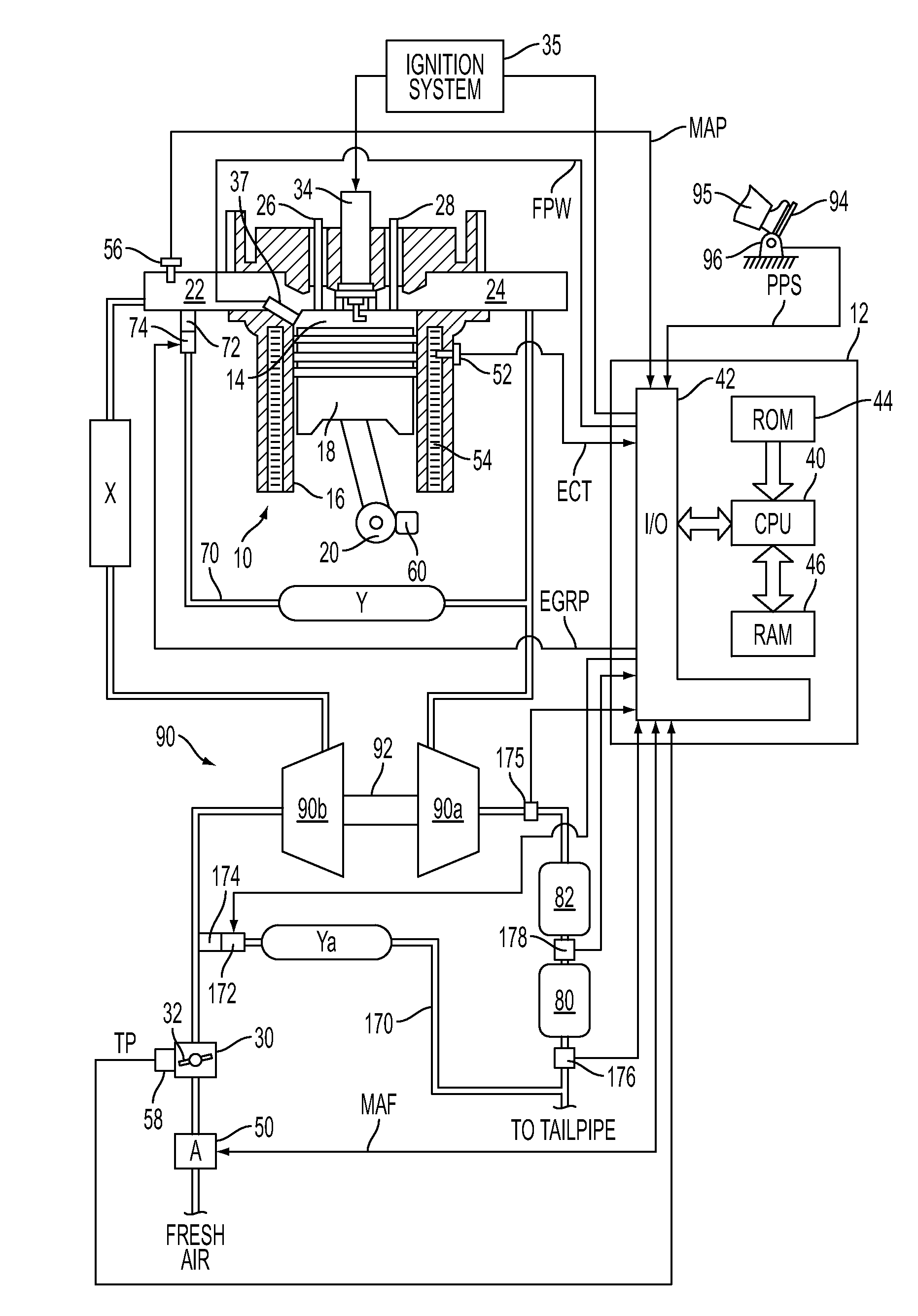
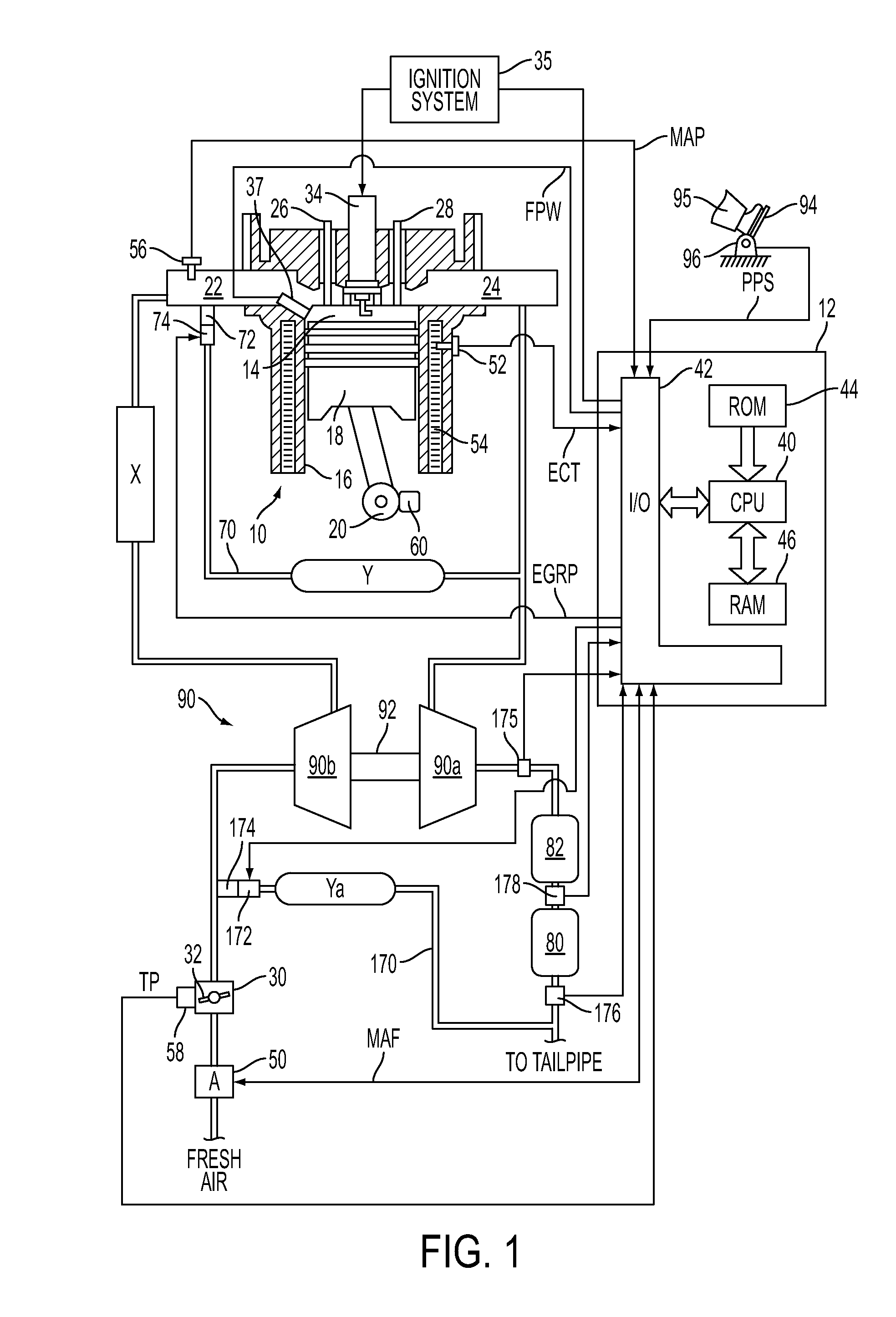
[0022]FIG. 1 shows an exemplary embodiment of a gasoline direct injection engine system generally at 10. Specifically, internal combustion engine 10 comprises a plurality of cylinders, one cylinder of which is shown in FIG. 1. Engine 10 is controlled by electronic engine controller 12. Engine 10 includes combustion chamber 14 and cylinder walls 16 with piston 18 positioned therein and connected to crankshaft 20. Combustion chamber 14 communicates with an intake manifold 22 and an exhaust manifold 24 via respective intake valve 26 and exhaust valve 28. Intake manifold 22 communicates with throttle body 30 via throttle plate 32. In one embodiment, an electronically controlled throttle can be used. In one embodiment, the throttle is electronically controlled to periodically, or continuously, maintain a specified vacuum level in intake manifold 22. Note that throttle body 30 and throttle plate 32 may be located at a location downstream of compression device 90 in some applications. Alte...


PUM


Abstract

A system for filtering and oxidizing particulate matter produced by a gasoline direct injection engine is disclosed. In one embodiment, engine cylinder air-fuel is adjusted to allow soot to oxidize at an upstream particulate filter while exhaust gases are efficiently processed in a downstream catalyst.

Description

CROSS-REFERENCE TO RELATED APPLICATIONS [0001]This application claims priority from U.S. Provisional Patent Application No. 61 / 246,939, entitled “PARTICULATE FILTER SYSTEM AND METHOD FOR REGENERATING,” filed Sep. 29, 2009, the disclosure of which is hereby incorporated by reference in its entirety and for all purposes.TECHNICAL FIELD [0002]The present application relates to the field of automotive emission control systems and methods.BACKGROUND AND SUMMARY [0003]Direct injection gasoline engines offer improved efficiency because fuel injected directly into a cylinder can reduce cylinder charge temperature. As a result, additional air may enter a cylinder as compared to an equivalent cylinder that has port injected fuel. Consequently, engine power and efficiency may be improved. In addition, direct injection gasoline engines may exhibit improved transient fuel control because there is less tendency for fuel to collect at a cylinder intake port of a direct injection engine than for a ...

Claims


Application Information

Patent Timeline
Patent Type & Authority Applications(United States)
IPC IPC(8): F01N3/023F01N3/021
CPCF01N3/023F01N3/101F01N3/106F02D37/02F02D41/029Y02T10/22F02D41/1454F02D2200/0804F02D2200/0812F02P5/1502Y02T10/46F02D41/1441Y02T10/12Y02T10/40
Inventor HEPBURN, JEFFREY SCOTTRUHLAND, HELMUT HANSSPRINGER, MORITZ KLAUSLORENZ, THOMASLOUVEN, GEORG
Owner FORD GLOBAL TECH LLC
Why Eureka
Try Eureka