

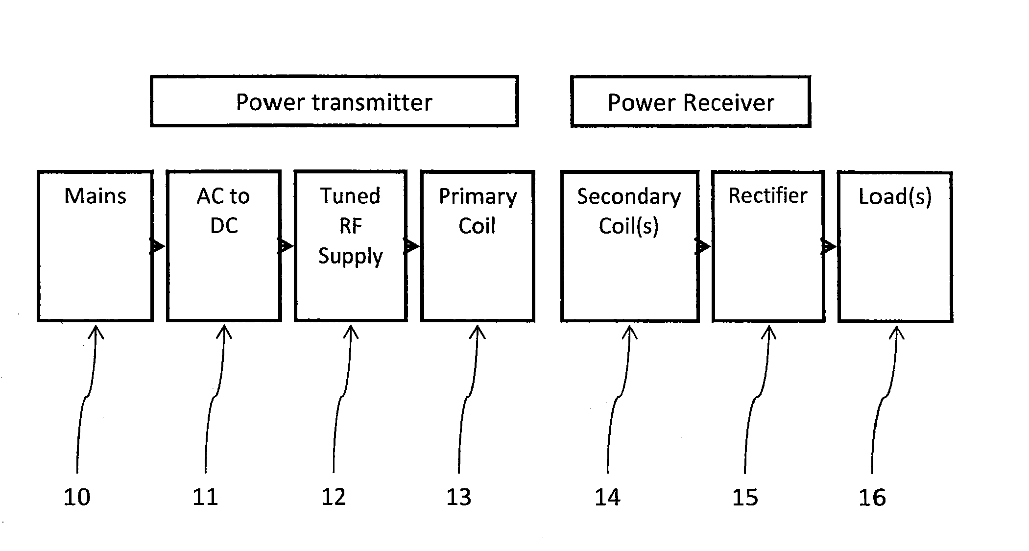
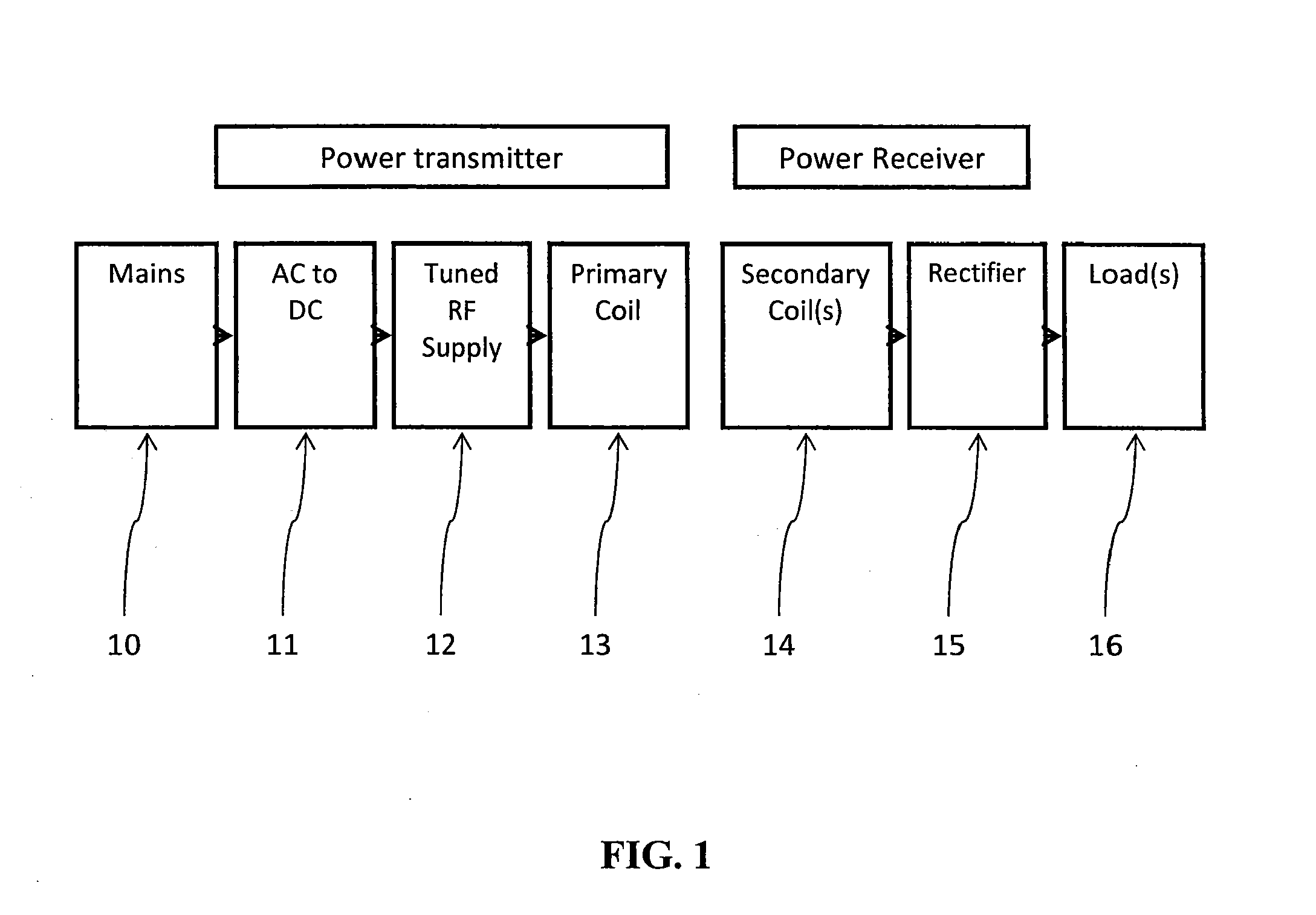
Method and apparatus for contactless power transfer
a technology of contactless power transfer and power supply, which is applied in the direction of transformers, inductances, safety/protection circuits, etc., can solve the problems of reducing efficiency, power delivery, or both, and the weakness of the primary and secondary coils, etc., and achieves the difficulty of implementing the contactless power system
- Summary
- Abstract
- Description
- Claims
- Application Information
AI Technical Summary
Benefits of technology
Problems solved by technology
Method used
Image

Examples
example 1
A high power, high-efficiency contactless power transfer system using the impedance transformation network and has been designed and fabricated using the subject impedance transformation network. The contactless transfer system requires minimal control to achieve the desired power delivery profile across a wide range of load resistances, while maintaining high efficiency to which helps to prevent overheating of components. This embodiment of the subject system includes more than one active device with independent gate drive to control power delivery. The system is able to achieve power delivery of 295 W to a load of 50Ω with a DC voltage of 121.5V and current of 2.43 A. The input current was current-limited at 3.25 A. The system efficiency at maximum power output is 75.7%. The system operates at a minimum of 77% efficiency across load resistances ranging from 60 to Ω 140Ω which corresponds to a high output power state. The system can be scaled to achieve higher output power if the c...
example 2
A primary coil parallel capacitor value in a specific embodiment can meet two constraints.
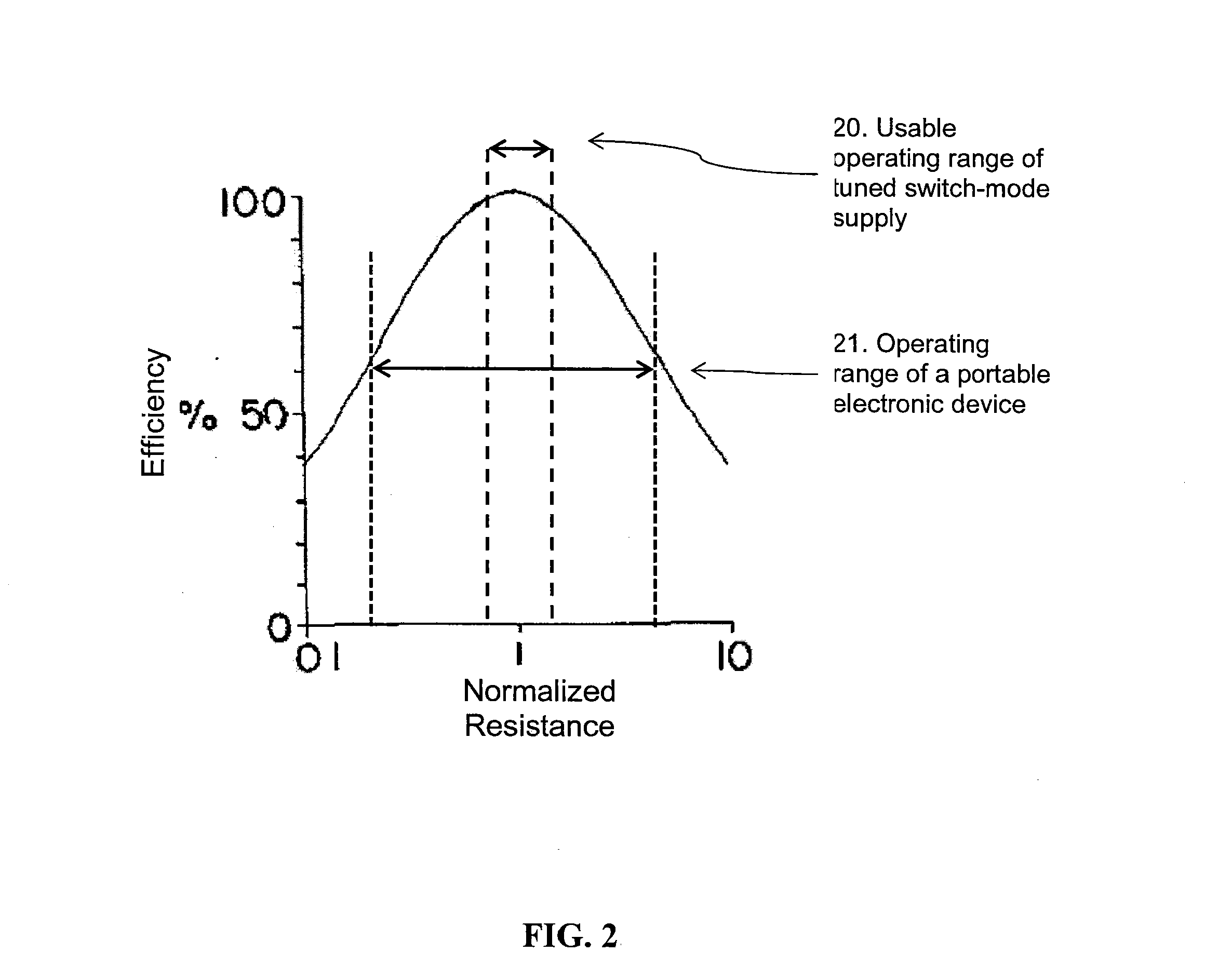
FIG. 24 offers a contrast to the preferred phase angle vs. load resistance trend shown in FIG. 21. The reference phase angle is approximately 80 degrees and decreases with load resistance. The phase angle 240 decreases with load resistance.
FIG. 25 shows the result of this mode of operation when there are no communication and control mechanisms in place. The power output increases with load resistance, which is exactly opposite the response of a fixed voltage DC supply 130 which is shown in FIG. 13.
FIG. 27 shows the real and reactive components of the impedance as seen looking into the receiver side impedance transformation network, where the impedance characteristic at this point is measured from a system operating in an undesirable range.
FIG. 28 shows the real and reactive components of the impedance as looking into the primary coil, where the impedance characteristic at this point is measured...
PUM
 Abstract
Description
Claims
Application Information