
Method and apparatus for determining radiation

a radiation and method technology, applied in the direction of liquid/fluent solid measurement, material electrochemical variables, instruments, etc., can solve the problems of low sensitivity to non-charged radiation, inability to produce real-time signals, and high manufacturing costs and/or complexity

Inactive Publication Date: 2011-04-07
MASSACHUSETTS INST OF TECH
View PDF16 Cites 52 Cited by
  • Summary
  • Abstract
  • Description
  • Claims
  • Application Information

AI Technical Summary

Benefits of technology

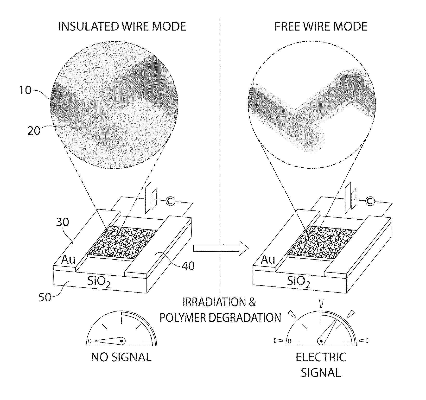
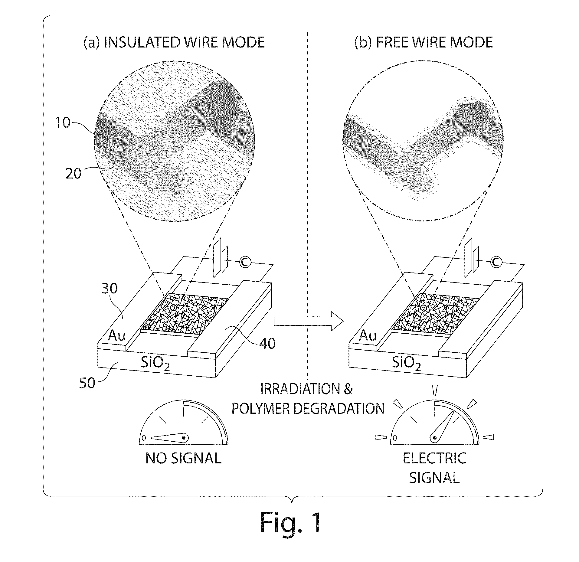
The present invention provides devices and methods for detecting ionizing radiation using a polymer material or nanostructures. The device or nanostructures undergo a change in a polymerization characteristic or the average distance between them when exposed to ionizing radiation, resulting in a detectable signal. This technology can be used in various applications to detect the presence of ionizing radiation.

Problems solved by technology

The most common systems for the detection and dosimetry of ionizing radiation usually have one or several of the following drawbacks: incapability to produce a real-time signal, expensive and / or complicated manufacturing, need for operation at low temperatures, low sensitivity to non-charged radiation, or voluminous size.
Although organic materials present the advantages of being easily processed, synthetic versatility, and relatively low cost, deployment of organic systems as small size ionizing radiation detectors and dosimeters has been traditionally limited to the detection of charged particles, owing to the low cross sections of elements incorporated in these molecules towards uncharged radiation.
Additionally, many devices for the detection and dosimetry of ionizing radiation suffer from drawbacks including inability to produce an in situ signal as is the case with film badges for dosimetry, expensive and / or complicated manufacturing, need for operation at low temperatures, low sensitivity to uncharged radiation, voluminous size like the Geiger counter, or the size and high voltages associated with 3He or BF3 proportional tubes.

Method used


Image

  • Method and apparatus for determining radiation
  • Method and apparatus for determining radiation
  • Method and apparatus for determining radiation

Examples


embodiment 1

wherein a, b, w, and n are each individually 0 or greater, R is alkyl, aryl, heteroalkyl, heteroaryl, each optionally substituted. In some cases, a, b, w, and n are each individually 1, or 2, or greater. In some cases, a and b are 1, 2, 3, 4, or 5. In some cases, a is 1 and b is 1, 2, 3, 4, 5. In some cases, R is alkyl, for example, butyl. In some cases, w is 1, 2, 3, 4, 5, or in a particular A specific example of a polymer is:

wherein a is 1, b is 3, and n is 40. The COOH group (or COO— group) may be used to associate with a metal-containing complex or species (e.g., gadolinium). For example, see Example 15.

[0060]In another example, the polymer material may comprise optionally substituted polyaldehydes (PALs), which may depolymerize in the presence of ionizing radiation to produce aldehyde species. PALs, as shown in FIG. 8, are a class of thermodynamically unstable, but kinetically stable, polymers, which can be synthesized by anionic polymerization. Typically, PALs are stabilized ...

examples and embodiments

[0116]Unless otherwise noted, the reactions described in the Examples were performed under an oxygen-free atmosphere of argon. Graduated flasks were used for polymerization reactions with condensed sulfur dioxide. Anhydrous solvents were obtained using a solvent purification solvent (Innovative Technologies). All other chemicals were of reagent grade from Sigma-Aldrich and were used as received, except for sulfur dioxide, which was purchased from Airgas, and triphenylbismuthine, which was purchased from Alfa. Cuprous Bromide was purified as described somewhere else. Multi-walled carbon nanotubes were donated by Bayer, AG (Baytubes 150 P, >95% purity).

[0117]NMR spectra were obtained on a Bruker Avance (400 MHz). NMR chemical shifts are given in ppm referenced to CHCl3 / TMS (7.24 ppm for 1H, 77.24 ppm for 13C), unless otherwise noted. High-resolution mass spectra (HRMS) were obtained on a Bruker Daltonics APEXII 3 Tesla Fourier Transform Mass Spectrometer at the MIT Department of Chemi...

example 1

[0119]

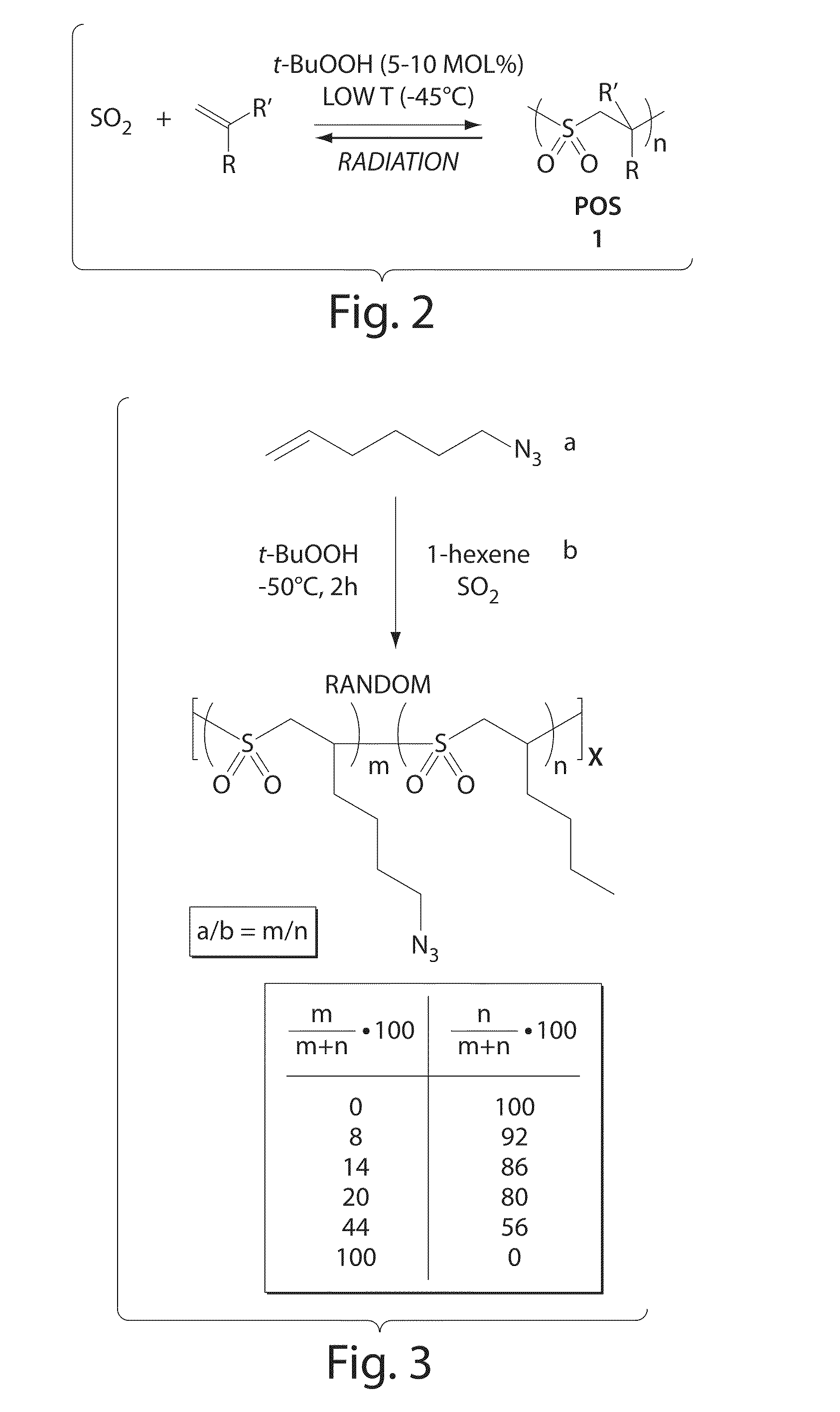
[0120]The following describes a general method for POS synthesis. A typical Poly (Olefin Sulfone) synthesis was carried out following literature procedures. In general, sulfur dioxide (6 mL) was condensed into a graduated vessel at −78° C. The reaction vessel was then transferred into a −45° C. bath. Olefin monomers were added to the reaction mixture in the desired ratio, and the solution was stirred for 5 minutes. Initiator for the polymerization (tert-Butyl hydroperoxide in decane, solution 5.0-6.0M, 5-10 mol % relative to total amount of olefin) was added, and the mixture was stirred at −45° C. for 2 h. The polymerization was stopped by pouring the reaction mixture into MeOH. The resulting white powder was redissolved in CHCl3 and reprecipitated from MeOH, then washed with MeOH. The white solid obtained was dried under vacuum.


PUM

PropertyMeasurementUnit
mol %aaaaaaaaaa
mol %aaaaaaaaaa
particle sizeaaaaaaaaaa

Abstract

The present invention relates to devices, systems, and methods for determination of ionizing radiation. In some embodiments, the devices comprise nanocomposite materials containing nanostructures (e.g., carbon nanotubes) dispersed in radiation sensitive polymers. In some cases, the device may include a conductive pathway that may be affected upon exposure to ionizing radiation. Embodiments described herein may provide inexpensive, large area, low power, and highly sensitive radiation detection materials / devices.

Description

STATEMENT REGARDING FEDERALLY SPONSORED RESEARCH OR DEVELOPMENT[0001]This invention was made with the support under the following government contract: DMR0706408 awarded by the National Science Foundation. The government has certain rights in the invention.FIELD OF THE INVENTION[0002]The present invention generally relates to devices and systems for determining ionizing radiation, and related methods.BACKGROUND OF THE INVENTION[0003]Detection and dosimetry of ionizing radiation are crucial in several fields such as energy, national security, biological and nuclear research, and in other advanced applications such as monitoring the attrition of materials in space travel. The most common systems for the detection and dosimetry of ionizing radiation usually have one or several of the following drawbacks: incapability to produce a real-time signal, expensive and / or complicated manufacturing, need for operation at low temperatures, low sensitivity to non-charged radiation, or voluminous ...

Claims


Application Information

Patent Timeline
Patent Type & Authority Applications(United States)
IPC IPC(8): G01N23/00G01N27/26B82Y15/00
CPCG01T1/04B82Y15/00
Inventor SWAGER, TIMOTHY M.LOBEZ, JOSE M.
Owner MASSACHUSETTS INST OF TECH
Learn More