
Methods, systems and devices for non-invasive ventilation including a non-sealing ventilation interface with a free space nozzle feature

a non-invasive ventilation and free space technology, applied in the field of ventilation therapy, can solve the problems of not being able to mechanically help, consuming a significant quantity of oxygen, and burdening the patient, and achieve the effect of convenient and efficient way of administering medication and promoting activity

Active Publication Date: 2011-04-28
BREATHE TECHNOLOGIES INC
View PDF28 Cites 84 Cited by
  • Summary
  • Abstract
  • Description
  • Claims
  • Application Information

AI Technical Summary

Benefits of technology

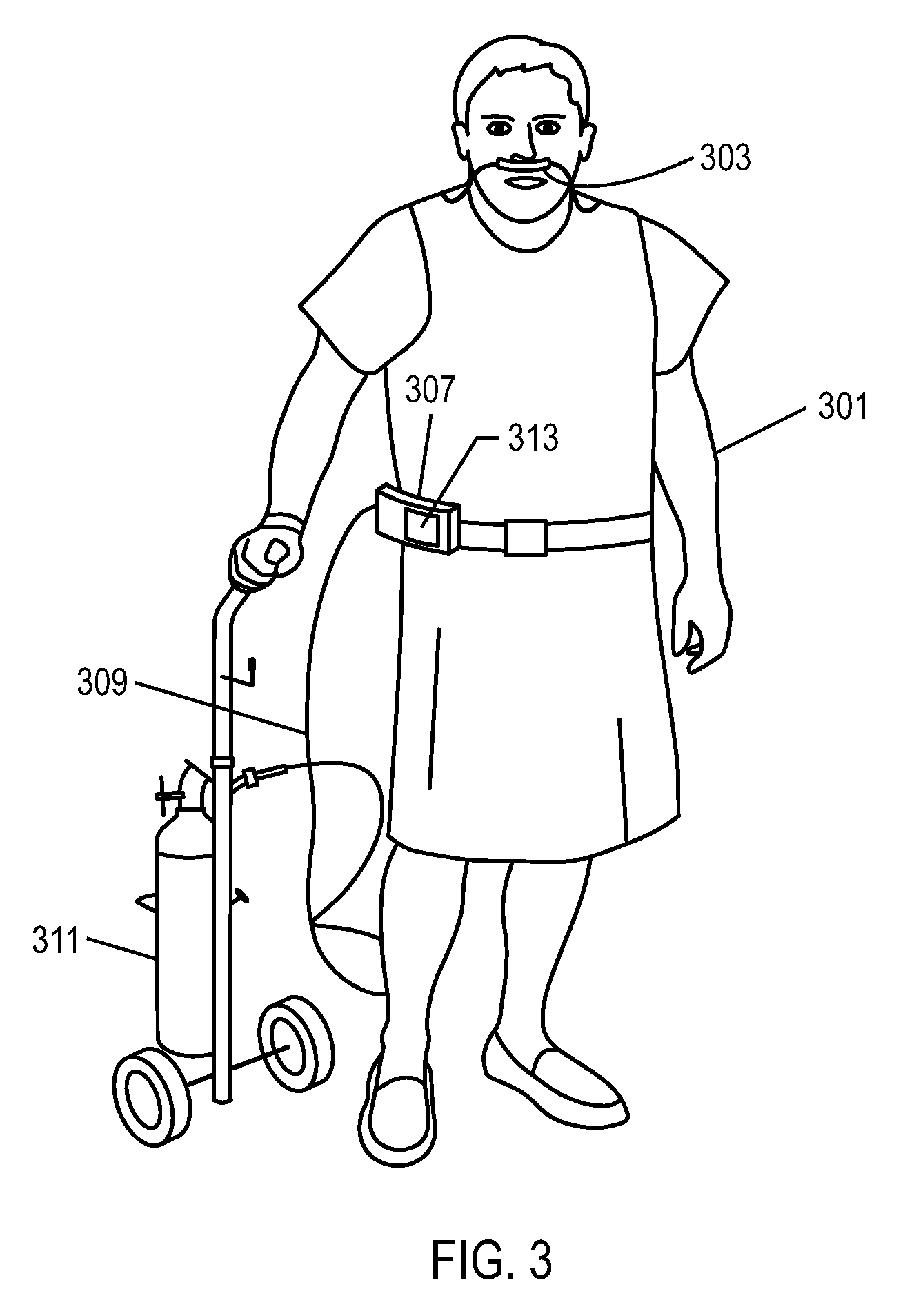
[0077]While FIG. 3 shows the patient using the invention for mobility, the invention can also be applied to sleep disordered breathing. In the later case, an advantage of the invention is that the mask and tubing is smaller than standard sleep apnea therapy masks and tubing. Additionally, the patient can have the sensation of breathing ambient air more directly making the therapy tolerable to the patient, rather than breathing through a machine, which is the sensation when using standard sleep apnea ventilation devices.
[0078]FIG. 4 is a block diagram describing an exemplary system of the invention. The exemplary system of FIG. 4 may be a wearable ventilator with portable gas source as shown in FIG. 3, or may be a different ventilator and / or gas source. Ventilator and patient interface features associated with the system are shown schematically. FIG. 4 depicts a non-invasive open nasal interface 400. The non-invasive open nasal interface will be described in various embodiments described herein, for example, in FIGS. 5-8B (curved nasal mask), FIGS. 9-15 (flexible joint), and FIGS. 16-25 and 29-31 (ergonomic configuration).
[0079]A ventilator module 401 may include or is in communication with several other functional accessories. The ventilator and the patient's internal anatomy from FIG. 3 are shown in schematic format in FIG. 4. A nasal airway pressure sensor 429 is typically included. A transmitter 403 may be included to transmit information regarding the patient, the patient's therapy, and the ventilator performance to a remote location for review, analysis, remote intervention, two-way communication, and archiving. For example, the patient's compliance with the therapy or utilization of the therapy can be monitored and assessed. Important information can be trended, for example the patient's breath rate, I:E ratio, oxygen usage, activity level, or depth of breathing. Also, information can be sent to a ventilator 433, such as for example, sending programming instructions for setting titration options for the ventilator output to meet the needs of the patient, or sending instructions to the patient. The patient can also send information or questions to a remote clinician through the ventilator and transmitter 403.
[0080]An oxygen source 407 and / or a compressed air source 409 can be included, typically external to the ventilator module 401. In certain embodiments, however, the oxygen source 407 and / or the compressed air source 409 can be internal to the ventilator module 401 if the therapy is being used for stationary use, for example, in the home. A blender 411 can be included to control the fractional delivered O2 in a gas delivery circuit 413. A pulse oximeter 415 can be used to titrate settings of the ventilator module 401 to meet the physiological needs of the patient, for example setting the correct oxygen blender setting or ventilator volume output. In addition to compressed supplies of oxygen and air gas, the ventilator module 401 can include internal or external air and oxygen generating systems 417, such as a compressor, pump or blower to create pressurized air, an oxygen generator and / or pump to create pressurized oxygen gas, and / or a compressed gas accumulator. The oxygen source can also be liquid oxygen, or a liquid oxygen generating system. An internal or external humidifier 405 can be included for extended uses of the therapy, or if using in dry climates.
[0081]As the therapy is frequently used to help ADL's, and to promote activity, a pedometer 419 and / or actigraphy sensor 421 can be included internal to or external to a ventilator module 401. Optional sensors may include a CO2 sensor 425, and / or an external breathing sensor unit 437. A CO2 sensing line 439 and / or an airway pressure sensing line 441 may be present. One or more other external sensors may be included. For example, other external sensors may include an external respiration sensor or respiration effort sensor 427, such as a respiratory muscle effort sensor, a chest impedance sensor 435, or other types of sensors, such as a tracheal or other microphone or vibration sensor 443 or acoustical or ultrasonic sensor. The one or more external sensors may be used either as a redundant sensor to a nasal airflow or nasal pressure sensor 429, or to complement the information obtained from the nasal airflow or nasal pressure sensor 429, or in place of the nasal airflow or nasal pressure sensor 429. An oral airflow breathing sensor may also be used, for example nasal airflow or nasal pressure sensor 429 may alternatively be an oral airflow sensor.
[0082]A drug delivery module 431 can be incorporated internally or externally to a ventilator module 401. Because of the challenges with current aerosolized drug delivery inhalers, the drug delivery module 431 can be used to propel and deposit medication particles deep in the respiratory system without a carrier propellant. Because the patient's using the therapy often may also require prescription medication, this may be a convenient and efficient way to administer the medication.

Problems solved by technology

There is a need for a minimally obtrusive nasal mask and ventilation system that delivers mechanical ventilatory support or positive airway pressure, and which unencumbers the patient.
For example, some nasal mask oxygen therapy systems have been developed for the purpose of delivering mixtures of air and oxygen by entraining air into the mask, however these are not considered ventilation therapy or respiratory support, because they do not mechanically help in the work of breathing.
These systems are inefficient in that they consume a significant quantity of oxygen, rendering them non-mobile systems and encumbering the patient.
While helpful in supporting the work of breathing, the patient interfaces used for MV are obtrusive and / or invasive to the user, and MV does not facilitate mobility or activities of daily living, therefore encumbers that patient and is a drawback to many potential users.
However, the patient cannot use their upper airway because the interface makes an external seal against the nose and / or mouth, and in addition the system is not mobile, the combination of which does not enable activities of daily living.
While effective, this therapy has poor patient compliance because the patient interface is obtrusive to the patient and the patient unnaturally breathes through both a mask and gas delivery circuit.
In summary, existing therapies and prior art have the following disadvantages: they do not offer respiratory support or airway support in a manner that unencumbers the patient and (1) is non-invasive, and un-obtrusive such that it allows for mobility and activities of daily living, (2) allows the sensation of breathing from the ambient surroundings normally, and (3) is provided in an easily portable system or a system that can be easily borne or worn by the patient.

Method used


Image

  • Methods, systems and devices for non-invasive ventilation including a non-sealing ventilation interface with a free space nozzle feature
  • Methods, systems and devices for non-invasive ventilation including a non-sealing ventilation interface with a free space nozzle feature
  • Methods, systems and devices for non-invasive ventilation including a non-sealing ventilation interface with a free space nozzle feature

Examples


Embodiment Construction

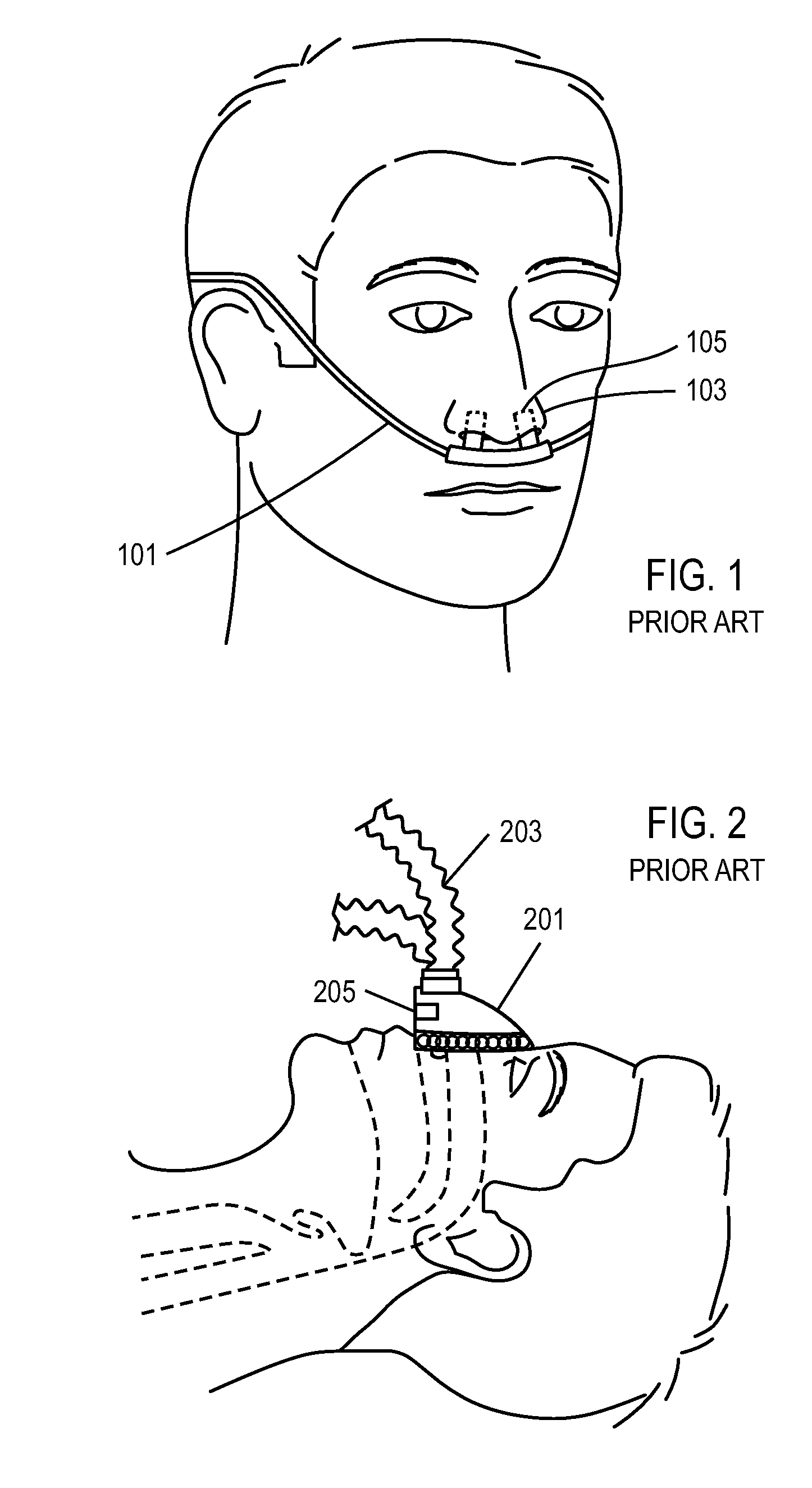
[0069]FIG. 1 shows a prior art conventional oxygen delivery cannula 101 for administering oxygen therapy. Extensions 105 on the cannula 101 are configured to enter nares 103. A proximal end (not shown) of the cannula 101 is connected to an oxygen delivery device that delivers continuous flow oxygen at 1-6 LPM to the user's nose, or delivers a bolus of oxygen upon detection of an inspiratory effort. The system of FIG. 1 does not mechanically support the work of breathing of the patient, and is not believed to be effective in preventing moderate to severe forms of OSA. The cannula of FIG. 1 is also used with another oxygen delivery therapy, high flow oxygen therapy (HFOT), in which more than 15 LPM of humidified oxygen is delivered at a continuous flow rate to the user's nose. Due to the high flow required for HFOT, the system is non-portable and the oxygen must be humidified.

[0070]FIG. 2 shows a prior art respiratory support therapy for non-invasive ventilation (NIV), using a nose ma...


PUM


Abstract

A system for supplying ventilatory support may include a nasal interface configured to communicate with a patient's nose while allowing the patient to breathe ambient air directly without flowing through the nasal interface. A nozzle may be associated with the nasal interface at a distance from a nose. The nozzle may be connectable to the gas delivery circuit and the gas delivery source. The nozzle may be capable of delivering gas into the nasal passage by creating negative pressure area near the nozzle and a positive pressure area near the entrance to the nose. A combination of gas from the gas delivery source and air entrained from the gas exiting the nozzle may provide ventilatory support.

Description

CROSS-REFERENCE TO RELATED APPLICATIONS[0001]This application claims priority to U.S. Provisional Patent Application No. 61 / 239,728, filed Sep. 3, 2009, U.S. Provisional Patent Application No. 61 / 255,760, filed Oct. 28, 2009, U.S. Provisional Patent Application No. 61 / 294,363, filed Jan. 12, 2010, and U.S. Provisional Patent Application No. 61 / 306,370, filed Feb. 19, 2010; the contents of which are incorporated by reference herein in their entireties. This application also claims priority to U.S. Non-Provisional patent application Ser. No. 12 / 753,846, filed Apr. 2, 2010, PCT Patent Application No. PCT / US2010 / 029871, filed Apr. 2, 2010, U.S. Non-Provisional patent application Ser. No. 12 / 753,851, filed Apr. 2, 2010, PCT Patent Application No. PCT / US2010 / 029873, filed Apr. 2, 2010, U.S. Non-Provisional patent application Ser. No. 12 / 753,853, filed Apr. 2, 2010, U.S. Non-Provisional patent application Ser. No. 12 / 753,854, filed Apr. 2, 2010, PCT Patent Application No. PCT / US2010 / 029874...

Claims


Application Information

Patent Timeline
Patent Type & Authority Applications(United States)
IPC IPC(8): A61M16/00
CPCA61M16/0666A61M16/0683A61M16/16A61M16/208A61M2016/0021A61M2016/0024A61M16/127A61M2205/8206A61M16/0677A61M16/0688A61M16/0858A61M16/101A61M2205/17A61M16/0833A61M16/085A61M2202/0208A61M2202/03A61M16/0672A61M2202/0007
Inventor CIPOLLONE, JOSEPHAGUIRRE, JOEYALLUM, TODDEGHBAL, DARIUSWONDKA, ANTHONY D.
Owner BREATHE TECHNOLOGIES INC
Learn More