Integrated Multi-Band Antenna

a multi-band antenna and integrated technology, applied in the direction of resonant antennas, antenna earthings, elongated active element feeds, etc., can solve the problems of inefficiency of receiving electromagnetic waves, increase fabrication costs, and too large antennas, and achieve superior transmission capability

Inactive Publication Date: 2011-05-05
ADVANCED CONNECTEK INC
View PDF3 Cites 23 Cited by
  • Summary
  • Abstract
  • Description
  • Claims
  • Application Information

AI Technical Summary

Benefits of technology

The primary objective of the present invention is to provide an integrated multi-band antenna, which adopts a design incorporating the capacitive coupling of conductors and the choke of an inductor member to form a loop monopole antenna, and which integrates the standard frequency bands of the low-frequency and high-frequency systems of the digital TV, and which achieves a miniaturized digital TV antenna spanning a wide range of frequency bands and having superior transmission capability.
Another objective of the present invention is to provide an integrated multi-band antenna, wherein two coupling regions generates capacitive impedance providing superior impedance matching for the frequency bands of the low-frequency and high-frequency systems, and wherein the inductor member has a serpentine and small-spacing path, and wherein the inductance can be varied to modify the impedance matching of the antenna, whereby the extension path of the radiation conductors is effectively reduced, and whereby the antenna system has wide transmission frequency bands and stable transmission quality.
In the present invention, a first coupling region and a second coupling region are respectively arranged on two opposite sides of the first conductor to form two conduction paths of the high-frequency signals. The two conduction paths respectively correspond to the standard frequency bands of the low-frequency and high-frequency systems of the digital TV. As to the standard frequency bands of the low-frequency system, the first conductor and a first branch of the second conductor form a first coupling region, and at least one inductor member is arranged near the first branch of the second conductor, wherein the high-frequency signal from a feeder cable is coupled from the first conductor to the second conductor in the first coupling region, whereby a loop antenna structure is formed to implement the standard frequency bands of the low-frequency system. The inductor member has a serpentine path with small spacings. Via adjusting the spacings, width and length of the inductor member, the inductance can be varied, and the impedance matching of the antenna can thus be modified. In cooperation with the capacitive impedance of the first coupling region, the antenna can have superior impedance matching. Thereby, the antenna of the present invention has wide transmission frequency bands and stable transmission quality.
As to the standard frequency bands of the high-frequency system, the first conductor and the terminal of the extension conductor form a second coupling region; adjusting the capacitance of the second coupling region not only can modify the input impedance of the antenna but also can reduce the size of the antenna; the first conductor, extension conductor and second conductor form a coupled-input monopole antenna structure, which can generates the standard frequency bands of the high-frequency system of the digital TV. Via fine tuning the sizes, lengths and volumes of the extension conductor and the second conductor, the frequency bands of the antenna system can have better impedance matching.
The inductor member is installed on the second conductor. When the feed-in signal of the frequency band of the high-frequency system is conducted from the first conductor, through the extension conductor, to the second conductor, the inductor member functions a signal choke interface to interrupt the transmission of the signal of the frequency band of the high-frequency system lest the signals of the high-frequency and low-frequency systems interfere mutually. The design of the serpentine paths of the two coupling regions and the inductor member can effectively shorten the paths of the radiation conductors and reduce the space occupied by the antenna layout. Therefore, the present invention can widen the frequency bands and miniaturize the antenna size at the same time.

Problems solved by technology

The circuitous antenna usually has an S form, and the adjacent portions thereof have opposite-direction currents, which result in the mutual interference of the electromagnetic signals and cause the inefficiency of receiving the electromagnetic waves.
Thus, the spiral antenna would increase the fabrication cost.
However, such a design results in too large an antenna and impairs the miniaturization of the antenna.
Further, the serpentine portions 121 and 141 have too long a length, which results in a complicated signal transmission path and an instable transmission quality.

Method used


Image

  • Integrated Multi-Band Antenna
  • Integrated Multi-Band Antenna
  • Integrated Multi-Band Antenna

Examples


first embodiment

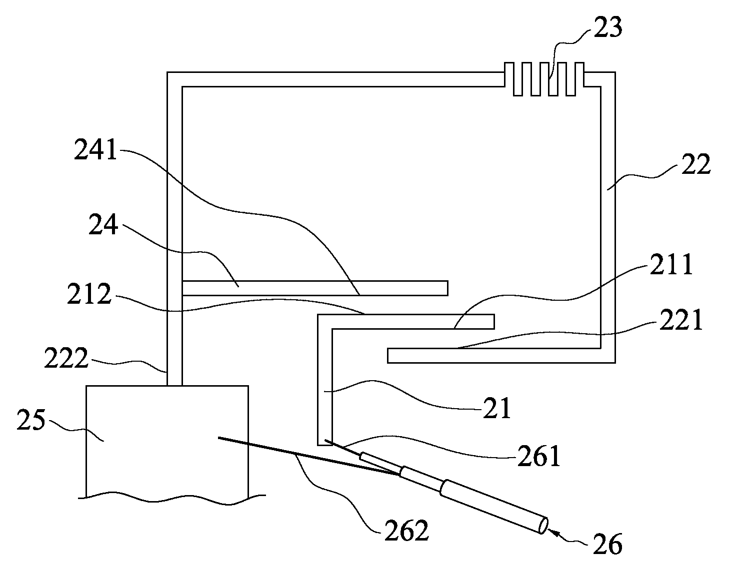
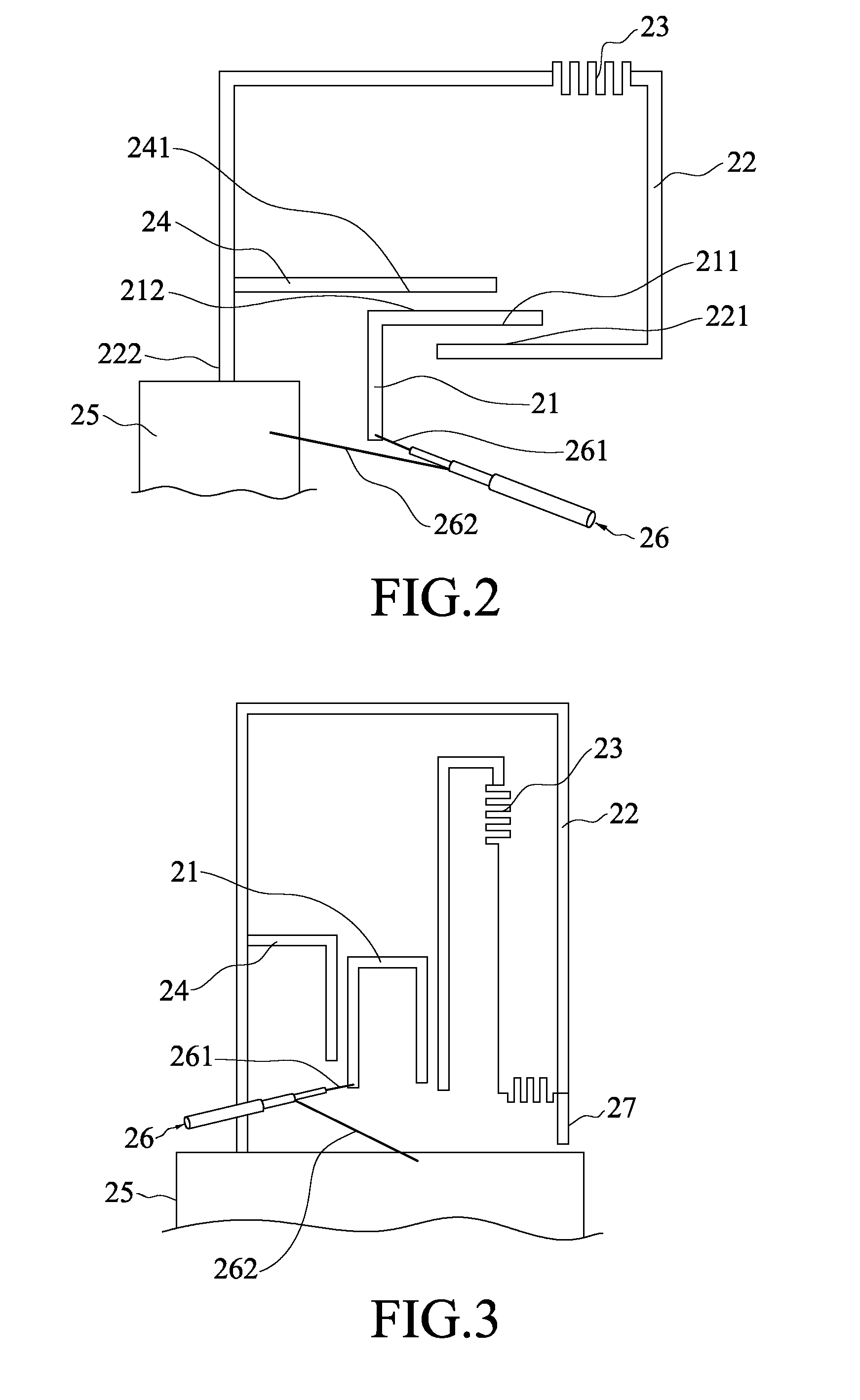
Refer to FIG. 2 a top view schematically showing an integrated multi-band antenna according to the present invention. The integrated multi-band antenna of the present invention comprises a first conductor 21, a second conductor 22, at least one inductor member 23, an extension conductor 24 and a grounding plane 25.

A first end 211 of the first conductor 21 and a first branch 221 of the second conductor 22 form a first coupling region. The inductor member 23 is arranged near the first branch 221 of the second conductor 22. The extension conductor 24 is a straight-line structure arranged near a second branch 222 of the second conductor 22 and extending therefrom to form a first terminal 241. The first terminal 241 and a second end 212 of the first conductor 21 form a second coupling region. The first coupling region and the second coupling region are respectively arranged on two opposite sides of the first conductor 21. The second branch 222 of the second conductor 22 is connected to t...

second embodiment

Refer to FIG. 4 a diagram showing the measurement result of the return loss of the antenna system according to the present invention, wherein the horizontal axis represents frequency, and the vertical axis represents dB. When the operation frequency bands of the antenna system are defined by the return loss greater than 5 dB, there are an operation frequency band S1 ranging from 100 to 220 MHz, which covers the VHF system, and an operation frequency band S2 ranging from 400 to 880 MHz, which covers the UHF system. The measurement result proves that the antenna system of the present invention can achieve the required operation frequency bands.

Refer to FIG. 5 a top view schematically showing that an integrated multi-band antenna according to a third embodiment of the present invention is integrated with a substrate of a digital TV. The third embodiment is basically similar to the first embodiment but different from the first embodiment in that the first conductor 21 (indicated by the ...


PUM


Abstract

An integrated multi-band antenna comprises a first conductor, a second conductor, at least one inductor member, an extension conductor, and a grounding plane. The first conductor and a first branch of the second conductor form a first coupling region. The inductor member is arranged near the first branch. The extension conductor is arranged near a second branch of the second conductor and extends therefrom to form a terminal. The terminal and first conductor form a second coupling region. The first and second coupling regions are arranged on opposite sides of the first conductor. The second branch connects to the grounding plane. The present invention adopts a design incorporating the capacitive coupling of the conductors and the choke of the inductor member, integrates the standard frequency bands of the low-frequency and high-frequency systems of the digital TV to achieve a miniaturized digital TV antenna spanning a wide range of frequency bands.

Description

BACKGROUND OF THE INVENTION1. Field of the InventionThe present invention relates to an integrated multi-band antenna, particularly to an antenna integrating the standard frequency bands of the high-frequency and low-frequency systems of the digital TV.2. Description of the Related ArtThe digital TV is going to be the indispensable apparatus of the portable wireless communication devices. The government departments, manufacturers, research organizations and universities are all devoted to developing miniature and high-performance antennae to achieve the objective that the users can enjoy high-quality digital TV programs anytime. For effectively receiving electromagnetic waves, an antenna needs to have a length of at least one fourth of the wavelength of the electromagnetic waves. The electromagnetic wavelength of the current digital TV ranges from 30 to 75 cm. The antenna will have a length longer than that of a mobile phone if the antenna is fabricated according to the aforemention...

Claims


Application Information

Patent Timeline
Patent Type & Authority Applications(United States)
IPC IPC(8): H01Q5/00H01Q1/48H01Q1/36H01Q5/321H01Q5/378
CPCH01Q7/00H01Q5/378H01Q5/321H01Q9/42
Inventor CHANG, YAO-YUANCHIU, TSUNG-WENHSIAO, FU-RENCHEN, WEN-SHYANG
Owner ADVANCED CONNECTEK INC
Why Eureka
Try Eureka