Vehicle operated on electric highway

Inactive Publication Date: 2011-05-05
SAKITA MASAMI
View PDF13 Cites 58 Cited by
  • Summary
  • Abstract
  • Description
  • Claims
  • Application Information

AI Technical Summary

Benefits of technology

[0007]An object of this invention is the provision of a vehicle operated in an electr

Problems solved by technology

This current collection method, however, is neither designed for high speed operations nor applicable to the ordinary automobile.
The electromagnetic induction power transfer syst

Method used


Image

  • Vehicle operated on electric highway
  • Vehicle operated on electric highway
  • Vehicle operated on electric highway

Examples


embodiment

Preferred Embodiment

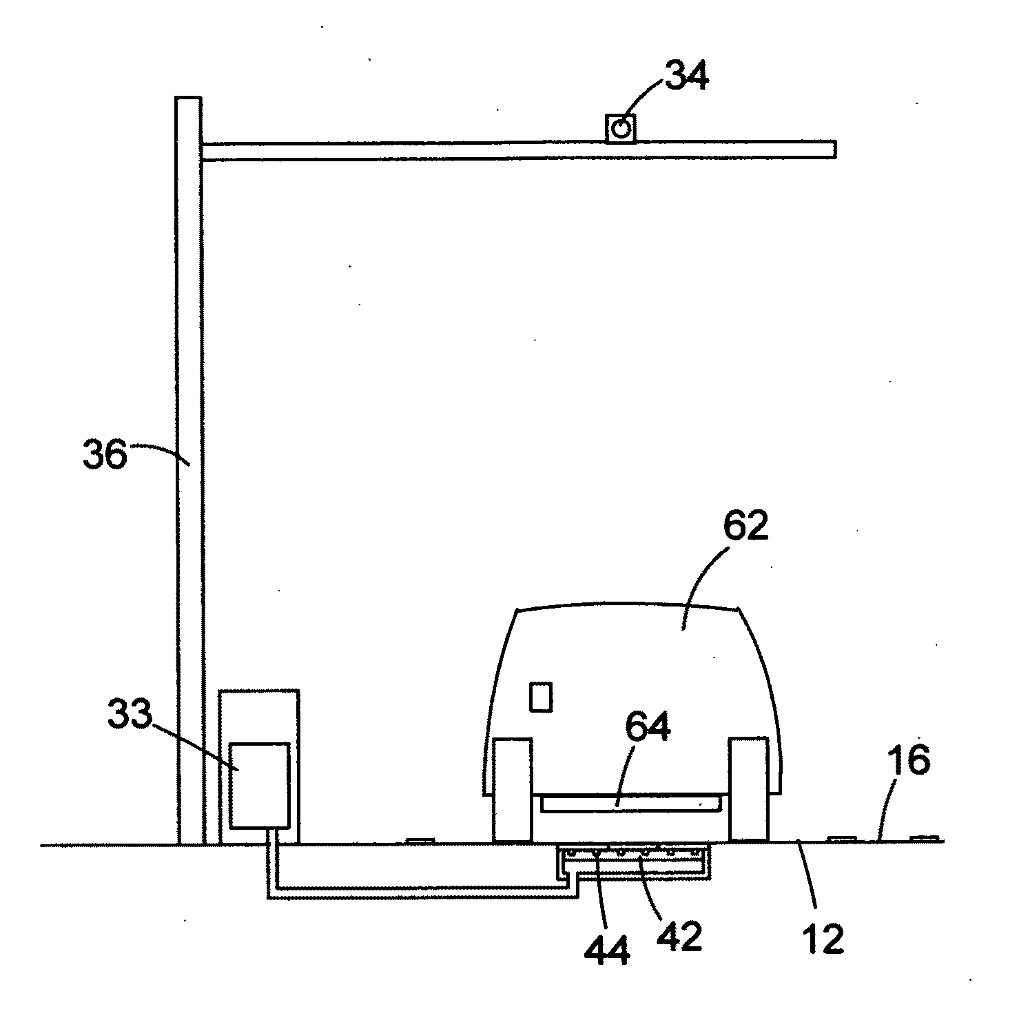
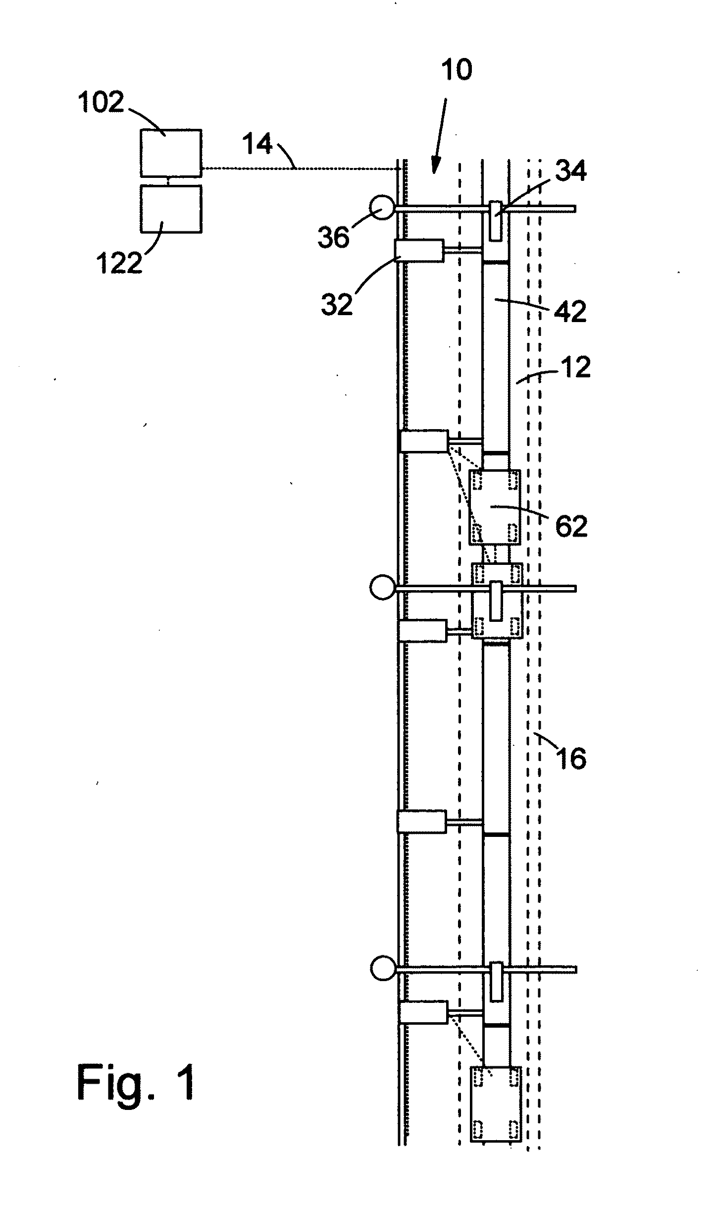
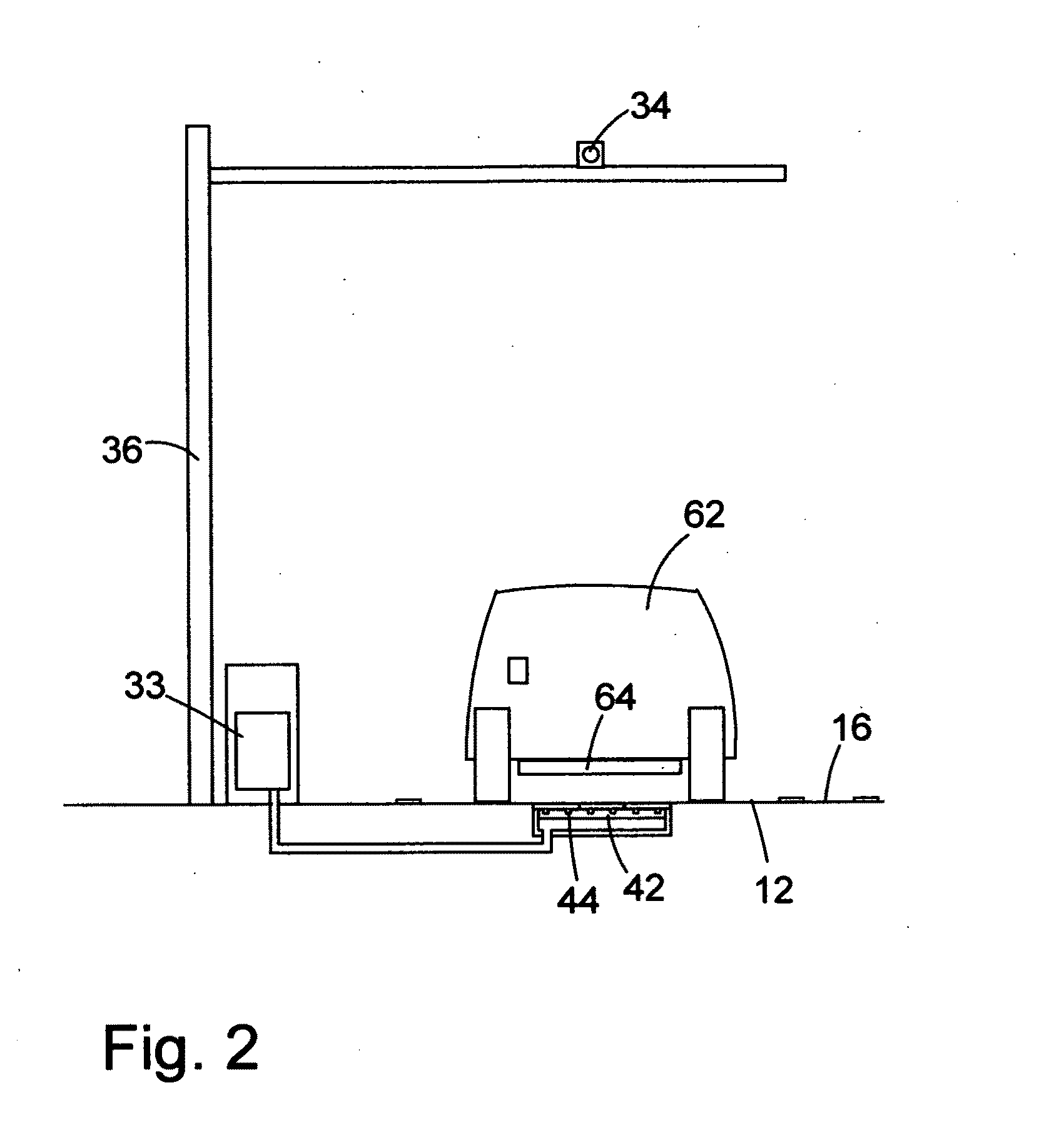
[0026]As shown in FIGS. 1 and 2, the electric highway system, in which the preferred embodiment of the vehicle 62 of the present invention is operated includes a roadside subsystem 10, a centralized system operation monitoring center 102 and an account processing center 122 that may be located in the same facility as the system operation monitoring center, a communication network 14 that connects the system operation monitoring center, the account processing center and the roadside subsystem, at least one electrified lane 12 that may be separated from the ordinary traffic lanes by a non-elevated divider strip 16 between them in a partially electrified highway, at least one power source such as a feeder station, and power cables that connect the power source and the roadside subsystem.

[0027]The roadside subsystem 10 includes a plurality of roadside conductor assemblies 42 disposed longitudinally serially in the electrified lane, each of which conductor assemblies ...

embodiment a

Alternative Embodiment A

[0053]As shown in FIGS. 8 and 9, the vehicle 62A of this alternative embodiment is a tall vehicle equipped with a power pick up means assembly that is a roof-top pantograph assembly 212. The coupler may be of the mechanical coupling means type 130 shown in FIGS. 5A through 5D and FIGS. 6A through FIG. 6C with male and female connecting means of litz power cables and connecting means of communication lines.

[0054]The roadside conductor assembly 42A includes a pair of catenary assemblies per electrified lane, wherein each of which pair includes a catenary 214 (or messenger wire) and a contact wire 216 that transfers electric power to the vehicles in the electrified lane(s). The roadside post 36A includes a vertical member (a pole) and a horizontal member from which horizontal member a segment of at least one pair of catenary assemblies is hung, and on which horizontal member a transducer type detector 210 and the camera 34A are mounted.

[0055]As shown in FIGS. 10...

embodiment b

Alternative Embodiment B

[0059]In another alternative embodiment, a group of vehicles of any type including those powered by conventional internal combustion engine is pulled in a train formation by a tall vehicle equipped with a power pick up means assembly in Alternative Embodiment A. The train is assembled and disassembled at a terminal that is connected to the electrified lane by flyovers. The towed vehicles in this case do not have an account to use the electric highway, and thus the driver of the towed vehicle must pay directly to the operator of the towing vehicle for the towing service.

[0060]The towed vehicle will be temporarily furnished with a detachable coupler assembly of the alternative design with power line connectors that include front and rear couplers connected by a metal beam and an onboard lateral location sensor that is connected to the towing vehicle by electric wires for electromechanically controlled brakes and a communications means. The towed vehicle must be...


PUM


Abstract

The vehicle operated in an electric highway system has an electric motor, at least one energy storage device, an on-board power pick up device, at least one coupler, at least one power meter, at least one on-board computer, an on-board part of a lateral location sensor, an on-board lateral position control mechanism, a longitudinal distance/speed sensor, and a longitudinal position control mechanism, and at least one communication device. The vehicle is able to operate and couple together with other vehicles automatically in the electrified lane of the electric highway system.

Description

FIELD OF THE INVENTION[0001]This invention relates generally to vehicles operated on electric highways.BACKGROUND OF THE INVENTION[0002]Electric power has been used to energize vehicles operated on the highway for a long time as seen in the trolley bus on the city street. The trolley bus is quiet, does not emit exhaust gas, and its current collection (or power transfer) method that uses the current collector poles and the overhead wires is very energy efficient. This current collection method, however, is neither designed for high speed operations nor applicable to the ordinary automobile.[0003]The electrified highway that does not use direct electrical conductive connection was tested in 1990 by the PATH (California Partners for Advanced Transit and Highways) administered at the Institute of Transportation Studies of the University of California at Berkeley in collaboration with Caltrans of the State of California. In the PATH experiment, electric power was supplied to the test veh...

Claims


Application Information

Patent Timeline
IPC IPC(8): G06F7/00B60K1/00B60M1/00
CPCB60K1/00B60K1/04B60L11/1801B60L11/182B60L11/1837B60L15/38Y02T90/121Y02T10/7005Y02T90/122Y02T90/128Y02T90/14Y02T90/16B60L2200/26B60M7/00Y02T10/7072B60L50/53B60L53/32Y02T10/70Y02T90/12
Inventor SAKITA, MASAMI
Owner SAKITA MASAMI
Why Eureka
Try Eureka