[0008]This need for an aircraft
system and method for improved ground
cooling efficiency is satisfied. Unlike known systems and methods, embodiments of the novel and nonobvious aircraft system and method for improved ground
cooling efficiency of the disclosure may provide one or more of the following advantages: provides an aircraft system and method for improved ground cooling efficiency of an electric based air conditioning system by use of a
recovery system which combines as the air conditioning system air source a first volume of cooler, less humid aircraft interior outflow air with a second volume of warm, humid outside aircraft exterior
ambient air; provides an aircraft system and method for improved ground cooling efficiency that adds at least one air flow path from the aircraft interior to an air
compression device inlet, where the air flow path includes at least one shutoff valve to enable the air flow path during ground operation and to disable the air flow path for flight operation; provides an aircraft system and method for improved ground cooling efficiency and improved cooling performance that enables the reduction of size, weight, and / or power of the air conditioning pack of the air conditioning system; provides an aircraft system and method for improved ground cooling efficiency in which the air conditioning packs and / or the power systems that power the air conditioning packs can be downsized while achieving the same
cooling capacity as known air conditioning pack systems, where such downsizing can result in reduced overall weight of the aircraft, reduced
assembly complexity, and reduced fuel consumption; provides an aircraft system and method for improved ground cooling efficiency that can improve passenger comfort through improved ground
cooling capacity, while providing for reduction in the air conditioning system weight, improved cooling performance, and reduced costs; provides an aircraft system and method for improved ground cooling efficiency that can use known equipment and does not require new or significantly re-
designed equipment, thus resulting in reduced costs; provides an aircraft system and method for improved ground cooling efficiency that can reuse and recirculate aircraft interior outflow air into the air
compression device inlet of the air conditioning system, thereby reducing the
total energy or work needed to reduce the temperature and cool the aircraft interior outflow air going back into the aircraft interior, provides an aircraft system and method for improved ground cooling efficiency that does not rely on main aircraft engine or APU bleed air for operation; and, provides an aircraft system and method for improved ground cooling efficiency that manages air flow during aircraft ground operations so as to maintain the aircraft's interior thermal environment ensuring
waste heat from primarily equipment cooling systems is exhausted overboard along with additional aircraft interior exhaust air flow which may contain odors such as from the lavatory, galley ventilation air,
nitrogen generation, or other systems.
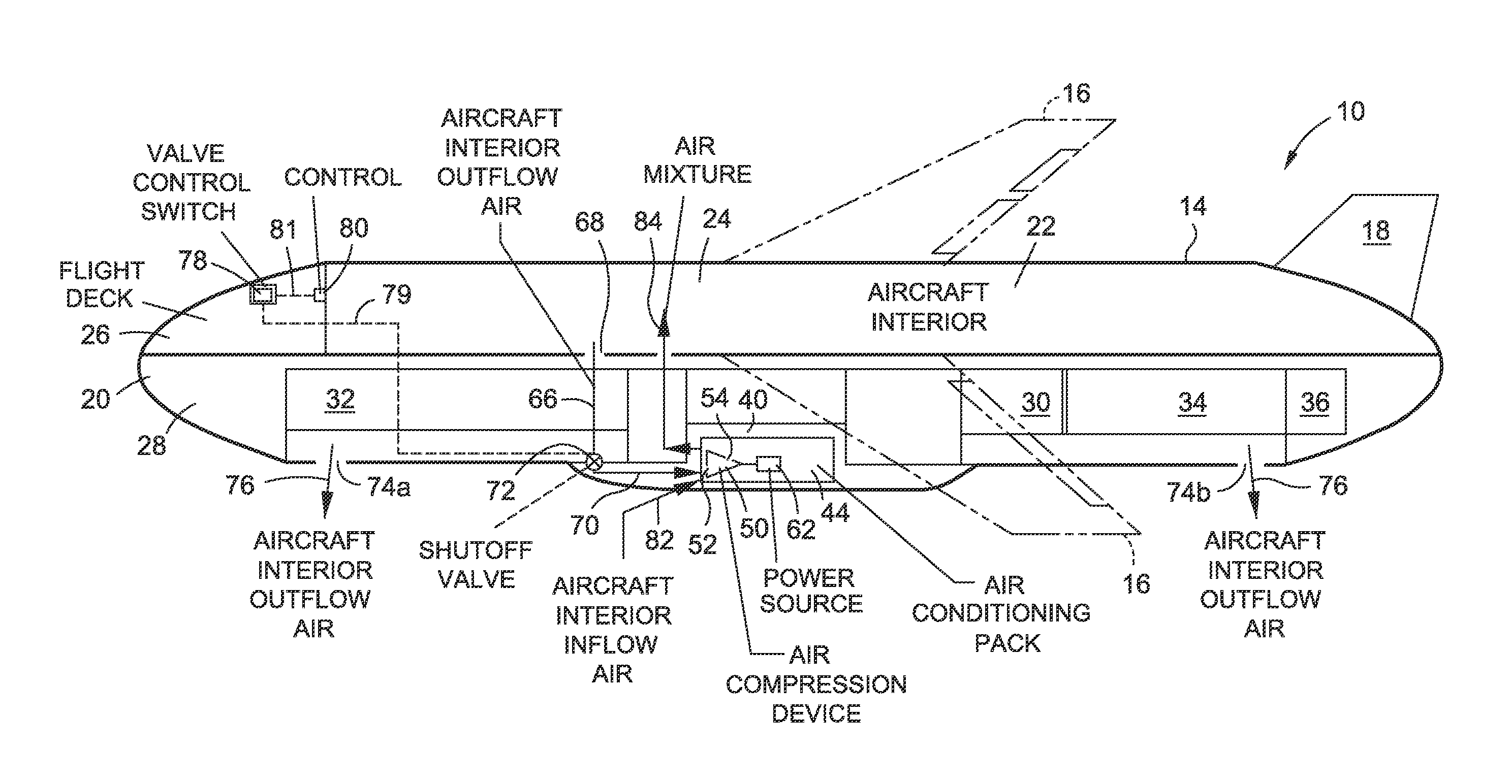
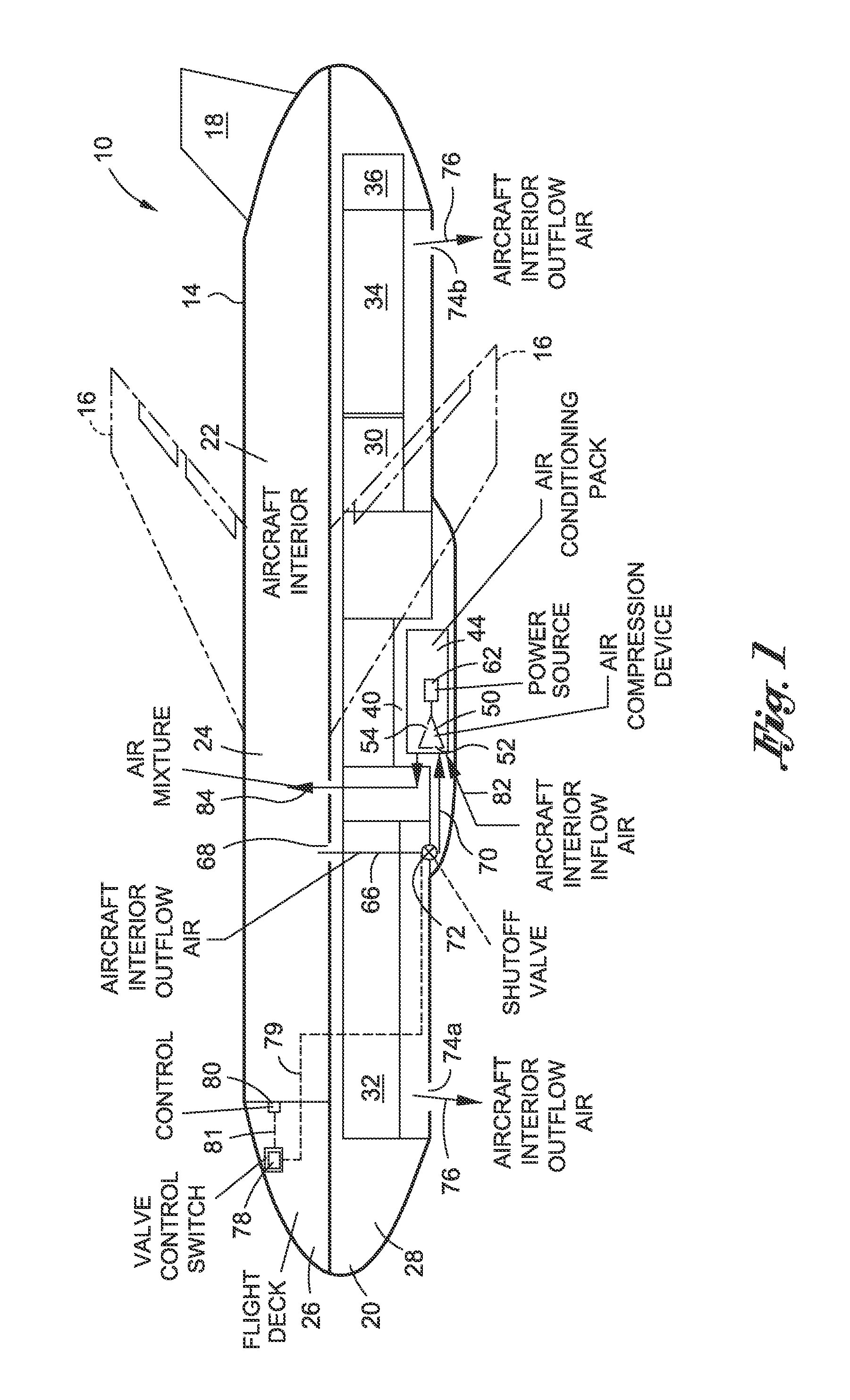
[0009]In an embodiment of the disclosure, there is provided an aircraft system for improved cooling efficiency. The system comprises at least one air conditioning pack coupled to an aircraft. The air conditioning pack has at least one air
compression device powered by at least one power source. The air compression device has an air compression device inlet. The system further comprises at least one air flow path for redirecting a first portion of a first volume of aircraft interior outflow air from an aircraft interior to the air compression device inlet. The air flow path includes a shutoff valve to enable the air flow path during ground operation of the aircraft and to disable the air flow path for flight operation of the aircraft. The air compression inlet mixes the first volume of aircraft interior outflow air with a second volume of aircraft exterior inflow air to form an air mixture. The air conditioning pack conditions and circulates the air mixture into the aircraft interior.
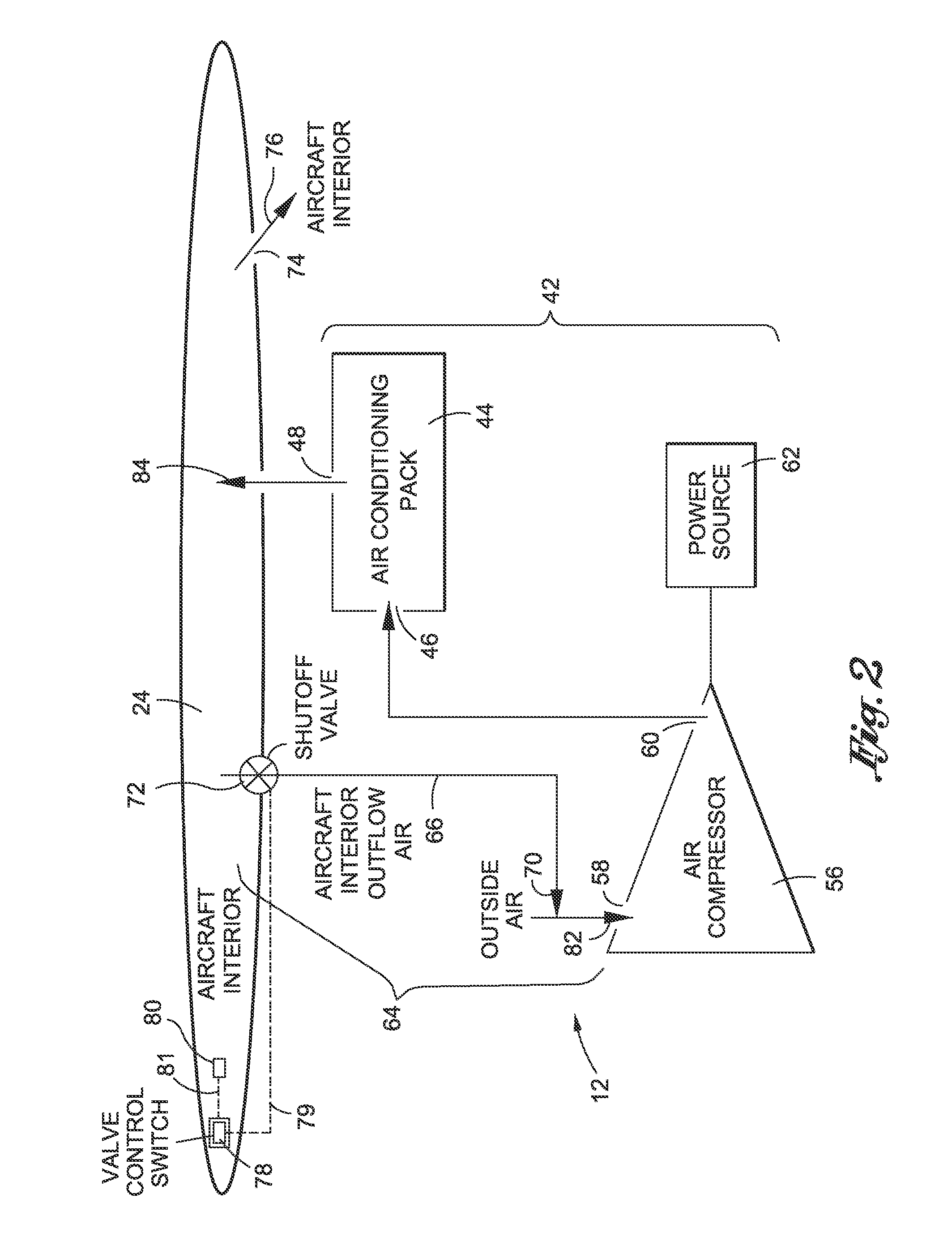
[0010]In another embodiment of the disclosure, there is provided an aircraft system for improved ground cooling efficiency. The aircraft system comprises an electric based air conditioning system coupled to an aircraft. The air conditioning system comprises at least one air conditioning pack having an air conditioning pack inlet and an air conditioning pack outlet. The air conditioning system further comprises at least one
air compressor that provides air to the air conditioning pack, the
air compressor having an
air compressor inlet and an air compressor outlet. The air conditioning system further comprises at least one
electric power source that provides
electric power to the air compressor. The aircraft system further comprises an aircraft interior
air recovery system coupled to the air conditioning system. The aircraft interior
air recovery system comprises at least one air flow path for redirecting a first portion of a first volume of aircraft interior outflow air from an aircraft interior to the air compressor inlet. The aircraft interior
recovery system further comprises a shutoff valve coupled to the air flow path to enable the air flow path during ground operation of the aircraft and to disable the air flow path for flight operation of the aircraft. The aircraft system further comprises an aircraft interior air outflow valve coupled to the aircraft interior for directing a second portion of the first volume of aircraft interior outflow air out of the aircraft. The aircraft system further comprises a valve
control switch in an aircraft flight
deck for enabling and disabling the shutoff valve. The air compression inlet mixes the first volume of aircraft interior outflow air with a second volume of aircraft exterior inflow air to form an air mixture. The air conditioning pack conditions and circulates the air mixture into the aircraft interior.
[0011]In another embodiment of the disclosure, there is provided a method for improving cooling efficiency in an aircraft. The method comprises directing via an air flow path a first portion of a first volume of aircraft interior outflow air from an aircraft interior to an air compression device inlet of an air conditioning pack coupled to the aircraft. The method further comprises taking in a second volume of aircraft exterior inflow air from outside the aircraft into the air compression device inlet. The method further comprises mixing in the air compression device inlet the first portion of the first volume of aircraft interior outflow air with the second volume of aircraft exterior inflow air to form an air mixture. The method further comprises conditioning and circulating the air mixture with the air conditioning pack into the aircraft interior.
[0012]In another embodiment of the disclosure, there is provided a method for improving ground cooling efficiency in an aircraft. The method comprises directing via at least one air flow path a first portion of a first volume of aircraft interior outflow air from an aircraft interior to an air compression device inlet of an air conditioning pack coupled to the aircraft. The air conditioning pack comprises at least one air compression device powered by at least one power source. The method further comprises directing a second portion of the first volume of aircraft interior outflow air from the aircraft interior to outside of the aircraft. The method further comprise taking in a second volume of aircraft exterior inflow air from outside the aircraft into the air compression device inlet. The method further comprises mixing in the air compressor inlet the first portion of the first volume of aircraft interior outflow air with the second volume of aircraft exterior inflow air to form an air mixture. The method further comprises conditioning and circulating the air mixture with the air conditioning pack into the aircraft interior. The method further comprises
coupling a shutoff valve to the air flow path to enable the air flow path during ground operation and disable the air flow path for flight operation. The method further comprises providing a valve
control switch in an aircraft flight
deck to enable or disable operation of the shutoff valve.

