[0017]The present invention is based on the finding that the simplest, and at the same time most efficient
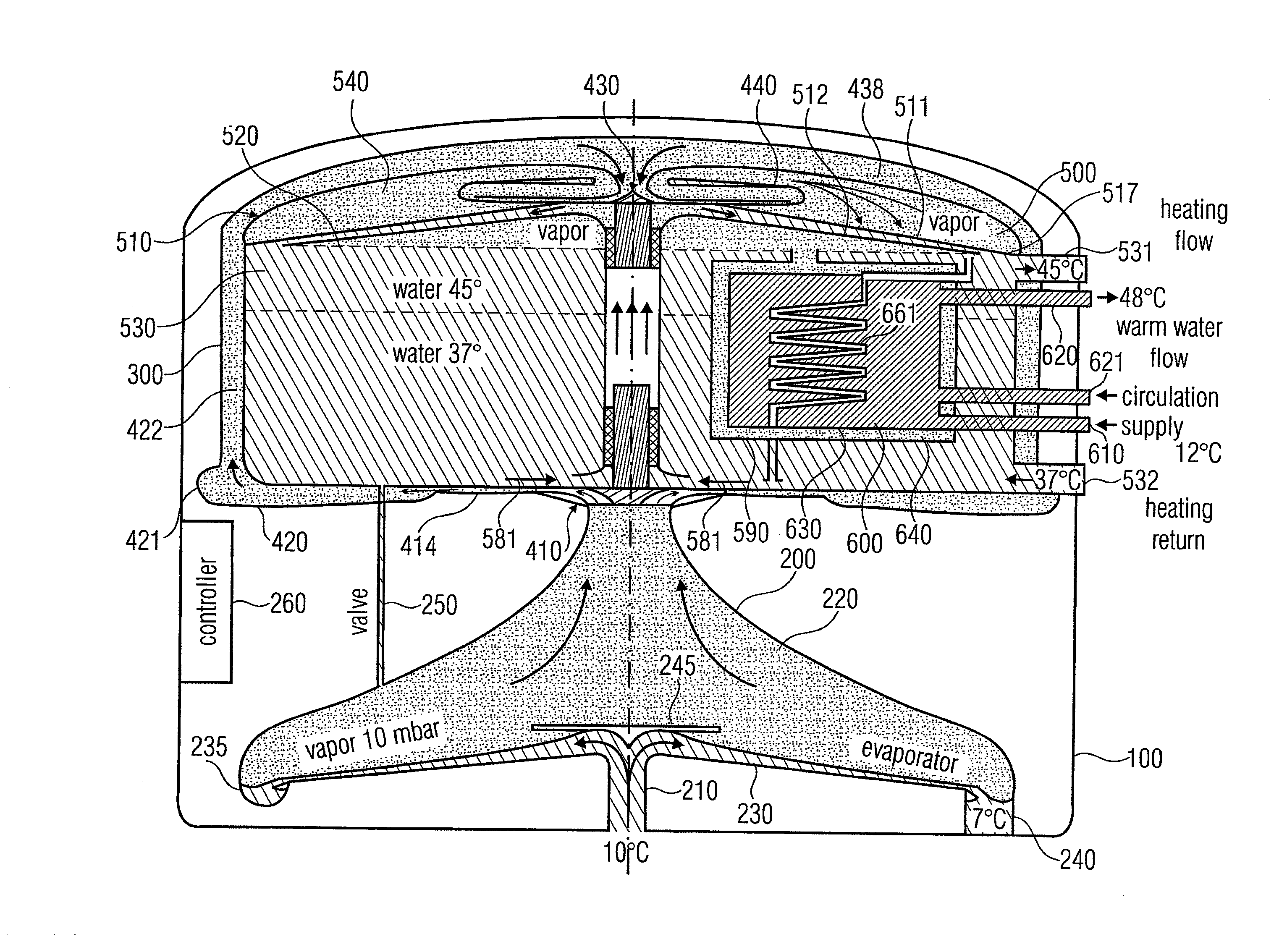
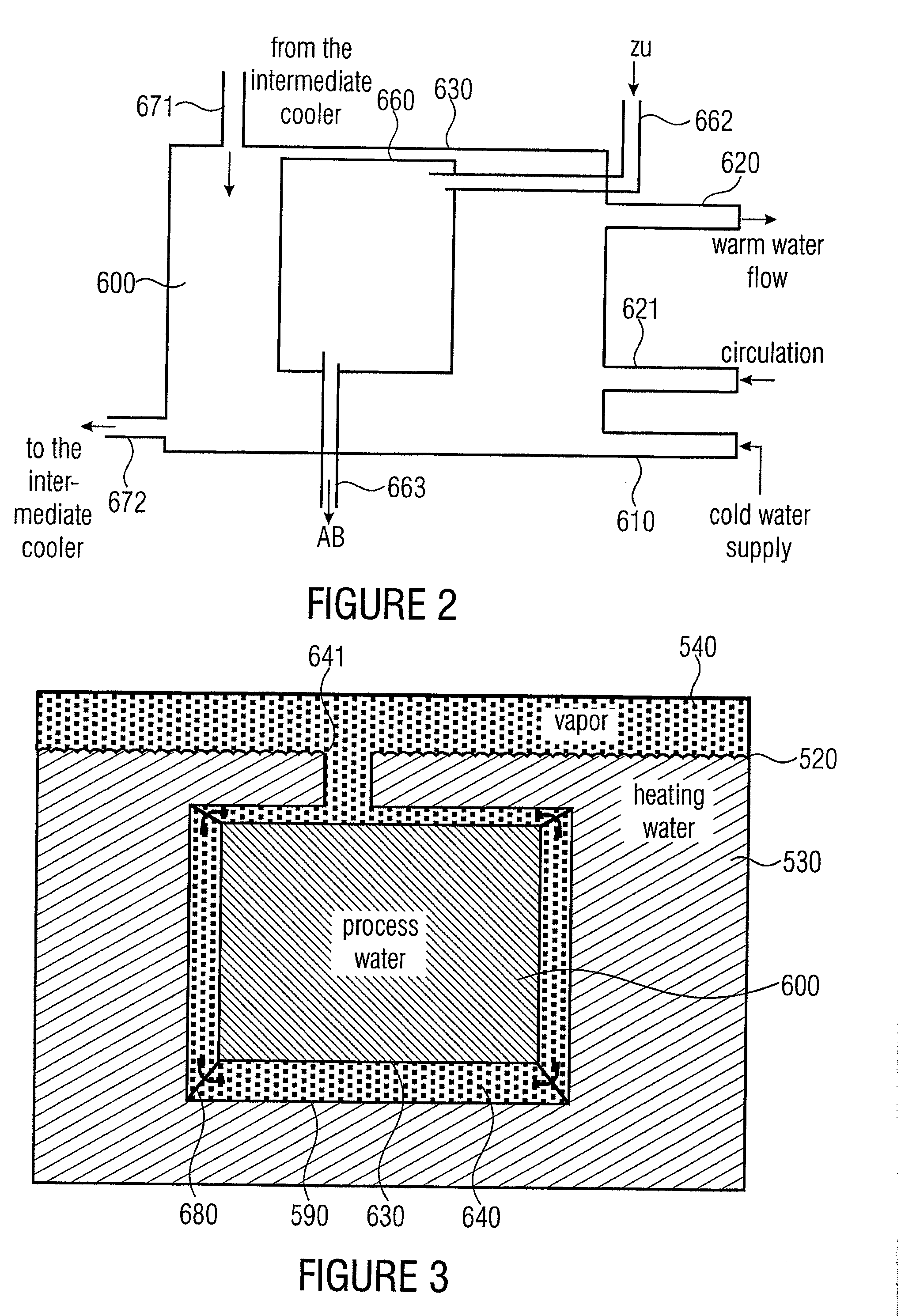
accommodation of the process water tank is achieved in the working fluid space of the liquefier. The working fluid space and the process water tank are arranged so that the process water tank has a wall spaced from a wall of the working fluid space. Hence, a gap, which at least partially comprises neither working fluid in liquid form nor process water, but is only filled with vapor, is obtained between these two walls. This vapor may be the same compressed working vapor that is transported into the liquefier from the compressor. This compressed working vapor fills the gap between the process water tank and the working fluid space.
[0020]In an embodiment, the heat pump is operated with water. As compared with the
atmospheric pressure, even compressed vapor, as is present in such a heat pump, has relatively low pressure, such as 100 mbar (100 hPa). Hence, the insulating effect between the process water tank and the liquefied working fluid is increased even more as compared with higher pressures of the vapor. This is due to the fact that the insulating effect of a gas-filled gap becomes greater, the smaller the pressure of the gas becomes, with the best insulating effect being achieved when there is a vacuum in the gap.
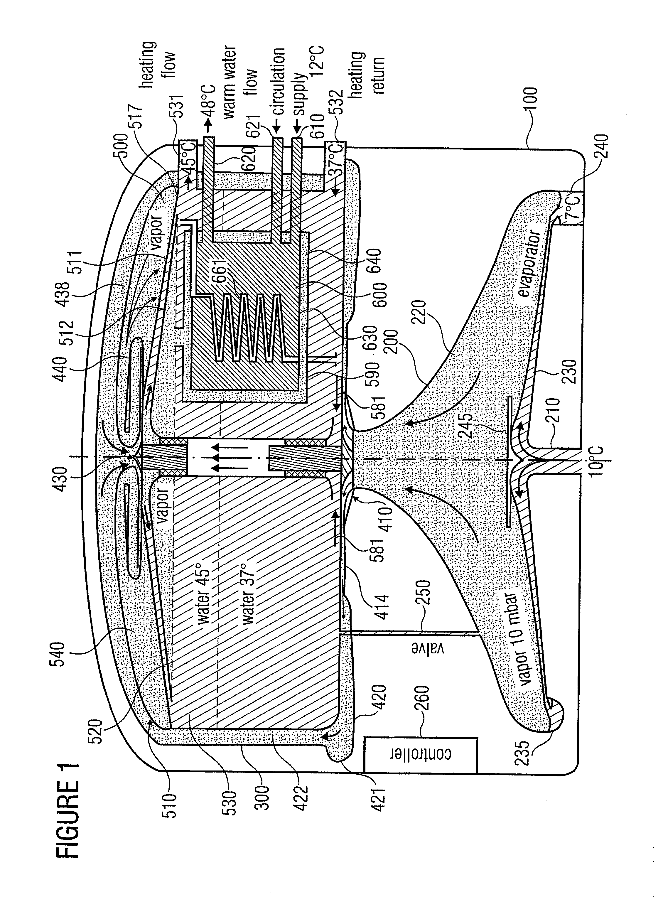
[0023]Furthermore, temperatures substantially higher than the liquefier temperatures are reached in the intermediate cooler due to the overheating properties, which additionally assists in maintaining hygienic conditions in the process water tank.
[0025]The arrangement of the process water tank in the liquefier, and particularly in the working fluid space of the liquefier, wherein the process water tank is, however, thermally separated from the working fluid space via a gap filled with gas or vapor, entails several advantages. One
advantage is that the process water tank does not need any additional space, but is contained within the volume of the working fluid space. Hence, the heat pump does not have any additional complicated form and is compact. Moreover, the process water tank does not need insulation of its own. This insulation would be necessitated if it was attached at another place. However, the entire working fluid space, and particularly the gap filled with gas and / or vapor, now acts as an inherent insulation. Furthermore,
heat losses, which may still occur, are uncritical because the entire heat given off by the process water tank reaches the liquefier itself, where it is often used as heating heat. Real losses are only
heat losses to the outside, i.e. to the surrounding air, which do not occur in the process water tank, however.
[0026]It is further advantageous that the gas filling for the gap between the wall of the process water tank and the wall of the working fluid space does not have to be specially manufactured. Instead, the working vapor itself, which is present in the liquefier anyway, is used advantageously to this end. Apart from the fact that vapor and / or gas have a better insulation effect than the liquefied vapor, i.e. the water and / or the liquefied gas, the insulation between the process water tank and the working fluid space is especially good when the heat pump works with water as the working fluid, because the pressure in the liquefier, albeit higher than the pressure in the
evaporator, is relatively low, such as at 100 hPa, which corresponds to medium negative pressure.
[0028]All these properties do not only lead to the fact that the heat pump as a whole becomes more compact and therefore more inexpensive and better to
handle, but also to the fact that the losses of the heat pump are minimized further. All the heat losses from the process water actually are no real losses, because the heat only reaches the liquefier space and is beneficial there for heating the
heating cycle. Nevertheless, however, it is easily possible, due to the good insulation, to maintain a higher temperature in the process water tank, at least in the upper region, than is present in the liquefied working fluid, because a higher temperature is generated in the intermediate cooler, which temperature is, for example, directly given off to the process water, i.e. without a
heat exchanger therebetween, and is fed to the process water tank in the upper region, which is where the warmest layer of the process water tank is located.

