
Solar cell structure

a solar cell and structure technology, applied in the direction of capacitors, solid-state devices, electrolytic capacitors, etc., can solve the problems of reducing the efficiency of solar cells, large loss of energy in heat, and heating of solar cells, and achieve the effect of improving the efficiency of transparent solar cells

Inactive Publication Date: 2011-05-19
BASF AG
View PDF5 Cites 15 Cited by
  • Summary
  • Abstract
  • Description
  • Claims
  • Application Information

AI Technical Summary

Benefits of technology

[0014]It is an object of the present invention to improve the efficiency of transparent solar cells which absorb sunlight only weakly.
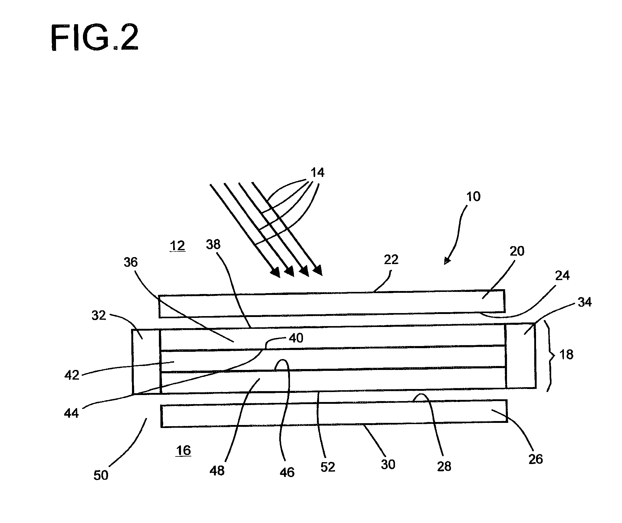
[0016]The fluorescent light generated in the at least one doped polymer layer shines through the at least one photovoltaic cell arranged there between the plates, and passes through the photovoltaic cell several times. Even without the polymer layer, the solar cells located between the layers advantageously absorb a certain fraction of the incident sunlight and convert it into current. By multiple irradiation through the transparent solar cells which are arranged between, above or below the doped polymer layers, a substantially higher fraction of the sunlight can be absorbed and converted into electrical current. Furthermore, the flat irradiation angle of the fluorescent light through the solar cell increases the absorption probability. The number of irradiations through the functional layer is increased by as small as possible a thickness of the layer structure.
[0017]The solar cell structure provided according to the invention comprises one or more solar cells which have only a low absorption, lying between 0-0.5, and only a very small layer thickness 10 nm-300 nm of the photoactive layer, and are distinguished by lower recombination losses.

Problems solved by technology

In conventional solar cells, for example solar cells made from silicon, a large part of the energy is lost in the form of heat.
The heating of the solar cell in turn reduces its efficiency.
None of the solar collectors described so far, comprising luminescent or fluorescent systems, has yet experienced commercial use, let alone development to the level of mass production, since on the one hand the organic dyes used suffer from degradation in sunlight, and on the other hand inorganic phosphorescent emitters do not have sufficient quantum efficiencies in order to overcome the absorption losses in the solar collector.
On the other hand, however, the quantum dots have a much lower quantum efficiency in the matrix, compared with fluorescent dyes.
To date, it has not been possible to produce plates with the requisite high optical efficiencies.
On the other hand, increasing the layer thickness reduces the efficiency because the excitons, electrons and holes generated after the light absorption must travel a longer distance to the electrodes and are subject to recombination losses on the way to the electrode.

Method used


Image

  • Solar cell structure
  • Solar cell structure
  • Solar cell structure

Examples


Embodiment Construction

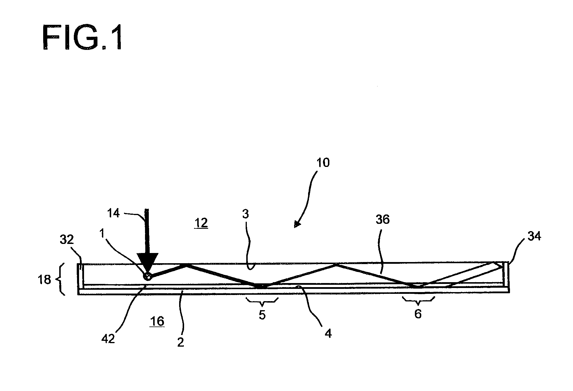
[0023]An alternative embodiment of the solar cell structure provided according to the invention can be found in the representation according to FIG. 1.

[0024]FIG. 1 shows a solar cell structure 10, which comprises a polymer layer. Below the polymer plate 36 there is a photovoltaic cell 42, underneath which a mirror surface 2 may in turn be arranged. Reference 14 denotes light incident on an illumination side 12, which strikes fluorescent molecules 1“dissolved” in a polymer layer 36. The incident light 14 is emitted by them in a stochastic distribution with a wavelength shift into all possible spatial directions. Only the part of this emitted light which is reflected, owing to total reflection at a first reflection surface 3 of the polymer layer 36, onto a second reflection surface 4 i.e. the upper side of the mirror surface 2, is of interest for the subsequent considerations. Besides the polymer layer 36, the solar cell structure 10 represented in FIG. 1—configured as a layer structu...


PUM


Abstract

The invention relates to a solar cell structure (10) having at least one transparent photovoltaic cell (42), in particular having a dye solar cell or a thin-film semiconductor cell. It comprises at least one polymer layer (36) which is provided with a fluorescent material, or a mixture of a plurality of fluorescent materials, and covers the at least one transparent photovoltaic cell (42).

Description

TECHNICAL FIELD[0001]The present invention relates to a solar cell structure which comprises one or more polymer layers doped with a fluorescent dye or a mixture of a plurality of fluorescent dyes, on or between which there are one or more transparent solar cells, transparent solar cells being distinguished in that the photoactive layer has an absorption of less than 80% at the absorption maximum.PRIOR ART[0002]The use of fluorescent solar collectors for converting the sun's spectrum into a spectrum that is better adapted to the spectral sensitivity of solar cells was already described in the 1970s, cf. U.S. Pat. No. 4,110,123 and Weber et al., Applied Physics, 15, 1976, 2299-2300.[0003]On the one hand, the energy of the sunlight can be utilized better by solar cells which have an improved spectral sensitivity. In conventional solar cells, for example solar cells made from silicon, a large part of the energy is lost in the form of heat. The band gap of crystalline silicon is 1.1 eV....

Claims


Application Information

Patent Timeline
IPC IPC(8): H01L31/0232
CPCH01G9/2031H01G9/2059H01G9/2068H01G9/209Y02E10/52H01L31/055H01L51/447Y02E10/542Y02E10/549H01L31/048H10K30/87H01L31/0445H02S40/20
Inventor RENNIG, ALFREDHAMMERMANN, MARKUSEICKEMEYER, FELIX
Owner BASF AG
Learn More