Gas distributor for a rotary kiln

a technology of rotary kiln and gas distributor, which is applied in the direction of furnaces, separation processes, lighting and heating apparatus, etc., can solve the problems of clogging of ports, limiting the flow of air into the reactor, and affecting the operation, control and maintenance of the reactor, so as to reduce the effect of direct impingement of gas jets and reduce pressure drop

Inactive Publication Date: 2011-05-19
REHMAT AMIRALI GULAMHUSSEIN +4
View PDF3 Cites 20 Cited by
  • Summary
  • Abstract
  • Description
  • Claims
  • Application Information

AI Technical Summary

Benefits of technology

In general, the diameter of the nozzles at any given circumference of the port assembly will be identical, although not necessary. However, the diameter of nozzles as they move into the kiln will become successively larger along the main conduit to reduce the pressure drop across them so that the gas flow can pass unhindered through all the nozzles.
In order to reduce the effect of direct impingement of gas jet onto the wall of the kiln, suitable muzzle devices can be installed

Problems solved by technology

Even though this art provides means of introducing air into the kiln either below the material charge of the bed or when the ports are above the bed, its operation, control, and maintenance is cumbersome.
If aforesaid apparatus is operated to process mixed size materials containing particles having smaller diameter than the port, these smaller particles may enter the ports and the associated piping causing the clogging of the ports and thereby restricting the flow of air into the reactor.
This sort of impairment also increases the necessity of maintenance and hence increases the downtime of the reactor.
While this improvement acts to prevent particulate material from entering the associated port pipe, some of the very smallest particulate material will eventually elude this screening mechanism and pass into the piping and eventually cause a restriction for the air flow into the reactor.
In this study it is implied that significant amount of carbon is left in the solid residue and unless used as fuel for indirect heating of the kiln shell, the process efficiency for converting biomass into fuel gas is greatly diminished.
This distributor has limited ability to cause intense mixing between the gas and solids in the reactor which is a prerequisite for causing optimum conversion of solid biomass and other solid carbonaceous fuels into gaseous fuel.

Method used


Image

  • Gas distributor for a rotary kiln
  • Gas distributor for a rotary kiln
  • Gas distributor for a rotary kiln

Examples


Embodiment Construction

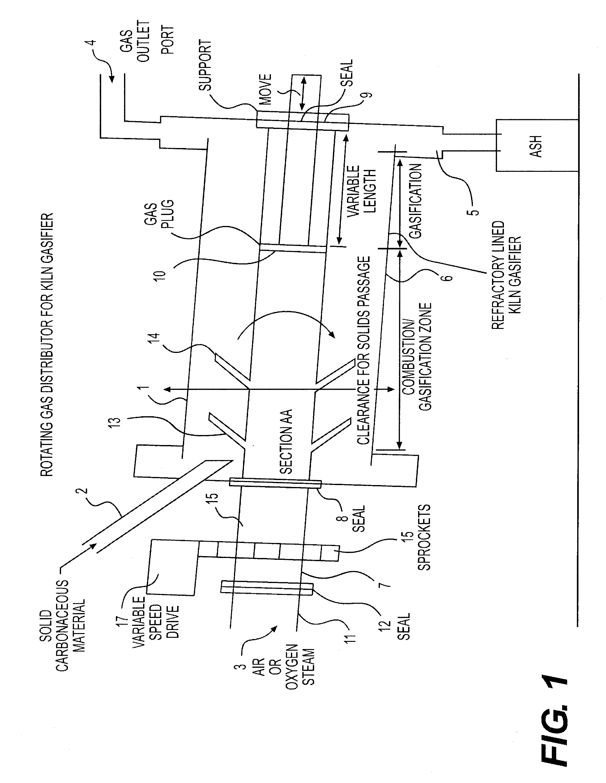
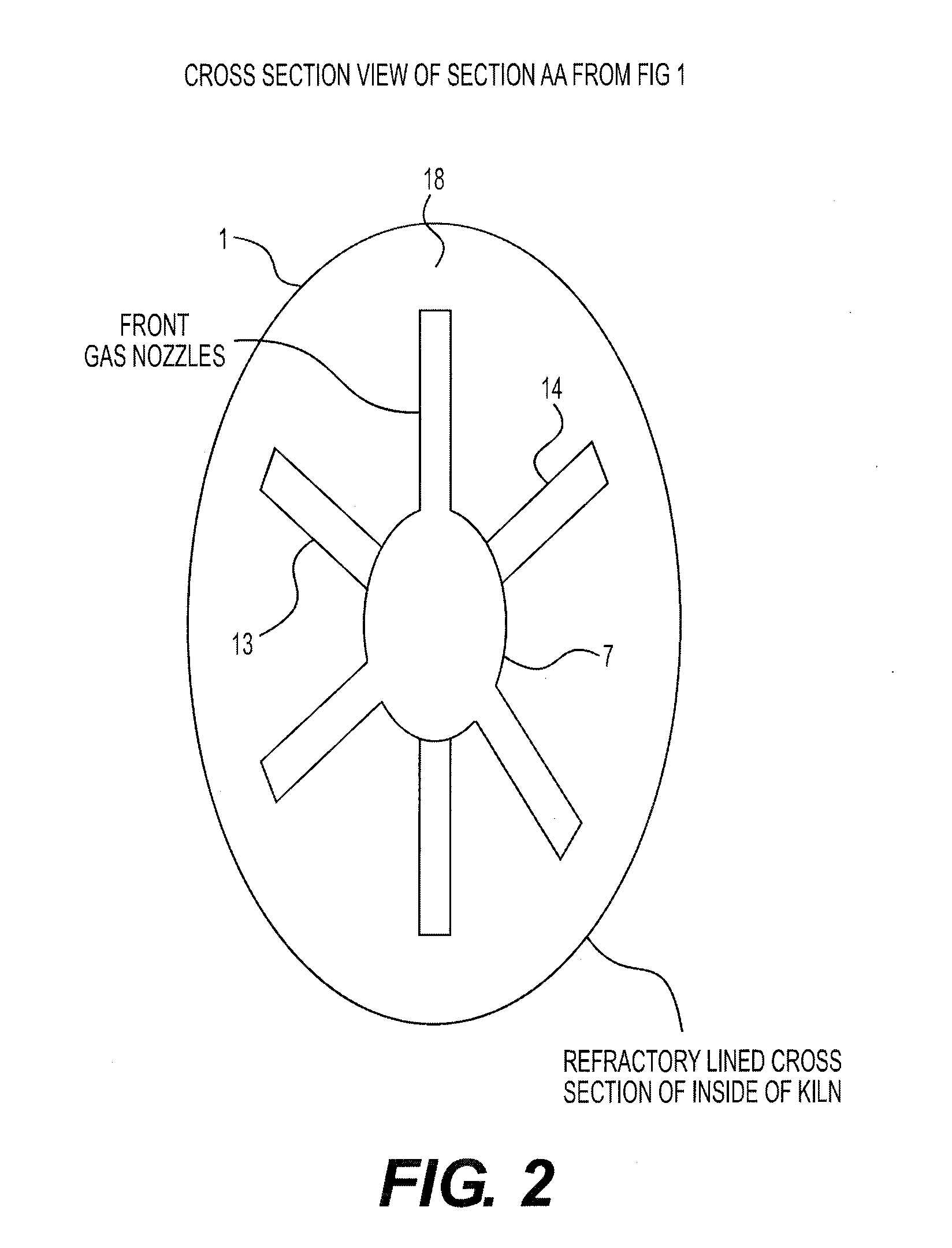
FIG. 1 depicts one of many types of rotary kiln apparatus with which the present invention can be practiced. Referring to FIG. 1, the rotary kiln gasifier 1 is a hollow refractory lined vessel with suitable inlets for feeding carbonaceous material 2, suitable inlet for feeding reactant gases such as air and steam 3, suitable outlet for fuel gas 4, and suitable outlet for ash 5. The rotary kiln depicted in FIG. 1 can also operate as combustor with equal effectiveness. The gasifier 1 should be large enough to gasify desired capacity of carbonaceous material and to provide adequate residence time for the gasification reactions between carbonaceous materials and the gaseous reactants. The interior of the gasifier 1 is preferably refractory lined 6 or alternatively surrounded by heat transfer devices such as tubes containing flowing liquids to absorb heat. The refractory lined kiln is preferred because the hot refractory retains heat and transfers that heat to the carbonaceous material c...


PUM

PropertyMeasurementUnit
angleaaaaaaaaaa
angleaaaaaaaaaa
lengthaaaaaaaaaa

Abstract

A rotating air distributor for rotary reactors such as rotary kilns for the gasification of biomass and other carbonaceous materials for efficient mixing and maximum conversion of solid biomass and other carbonaceous materials into synthesis fuel gas is disclosed. The invention includes a gas distribution port comprises of one main supply from which several discharge nozzles emerge at different angles and at different locations along the length of the reactor to provide distribution of gas throughout the intended length of the reactor. The discharge of gas from the gas distribution port is adjusted by the variable position of a plug inside the port that can be adjusted during the operation of the kiln to achieve optimum gas-solid interaction along the length of the reactor. The rotating action of the gas distribution port also facilitates and eases the passage of reacted biomass solid and other carbonaceous material residue through the reactor.

Description

BACKGROUND OF INVENTION1. Field of InventionThis invention relates to rotary reactors such as rotary kiln for the gasification of solid carbonaceous materials such as biomass and solid wastes and particularly to the gas distributor for introducing gases such as air, oxygen, and steam to the interior of the rotary kiln wherein this gas distributor assures gas solid mixing inside the reactor to promote gas solid reaction.2. General Background and the State of the ArtIn the last two decades or so, interest in biomass gasification has picked up as means of producing energy from renewable resources to supplement fossil fuels as well as to develop strategy for distributed generation for reasons of meeting energy security needs. This renewed interest has encouraged development of new and improved methods for making biomass gasification efficient and fuel gas generated from these cleaner in terms of its tar content. Biomass typically comprises collectable, plant-derived materials that may b...

Claims


Application Information

Patent Timeline
Patent Type & Authority Applications(United States)
IPC IPC(8): B09B3/00
CPCF23L7/00F27B7/36Y10T137/85938B01D35/005B01D35/308B01D2201/309B01D2201/347B01D2201/4092F02M37/22C01B3/02C10J3/005C10J2200/152C10J2300/0916C10J2300/0946
Inventor REHMAT, AMIRALI GULAMHUSSEINCOMLY, RENEE LYNKADWANI, AMJAD ABDULALIMATHEW, ALEXMATHEW, GEORGE
Owner REHMAT AMIRALI GULAMHUSSEIN
Why Eureka
Try Eureka