Process for the removal of carbon dioxide from a gas

Inactive Publication Date: 2011-05-19
SHELL OIL CO
View PDF5 Cites 14 Cited by
  • Summary
  • Abstract
  • Description
  • Claims
  • Application Information

AI Technical Summary

Benefits of technology

[0010]An important advantage of the process is that the CO2-rich stream is obtained at relatively high pressure. This facilitates the use of the CO2-rich stream for enhanced oil recovery or for reinjection into a subterranean formation or aquifer, with less equipment needed for further compression of the CO2-rich stream.
[0011]Still another advantage is that as regeneration takes place at elevated pressure the water content of the CO2-rich gas stream exiting the regenerator is reduced. This reduces the regenerator condenser duty and also reduces the reboiler energy requirement.
[0012]Another important advantage is that an aqueous solution is used, having a relatively low volatility. The solvent losses will be much less compared to processes using more volatile solvents such as ammonia. The presence of an accelerator enhances the

Problems solved by technology

Emissions of CO2 into the atmosphere are thought to be harmful due to its “greenhouse gas” property, contributing to global warming.
One disadvantage of the process described in WO 2006/022885 is that

Method used


Image

  • Process for the removal of carbon dioxide from a gas
  • Process for the removal of carbon dioxide from a gas

Examples


Example

[0019]An embodiment of the present invention will now be described by way of example only, and with reference to the accompanying non-limiting drawing in which:

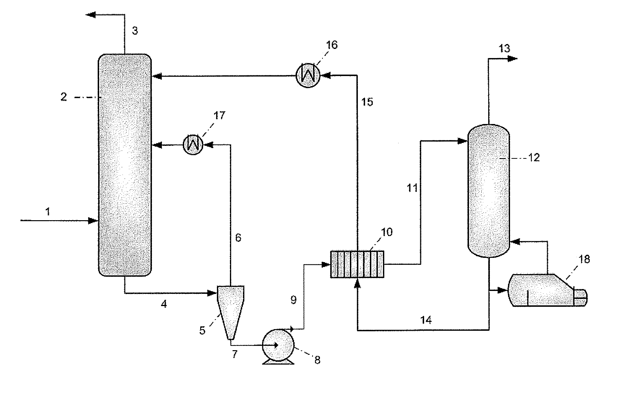
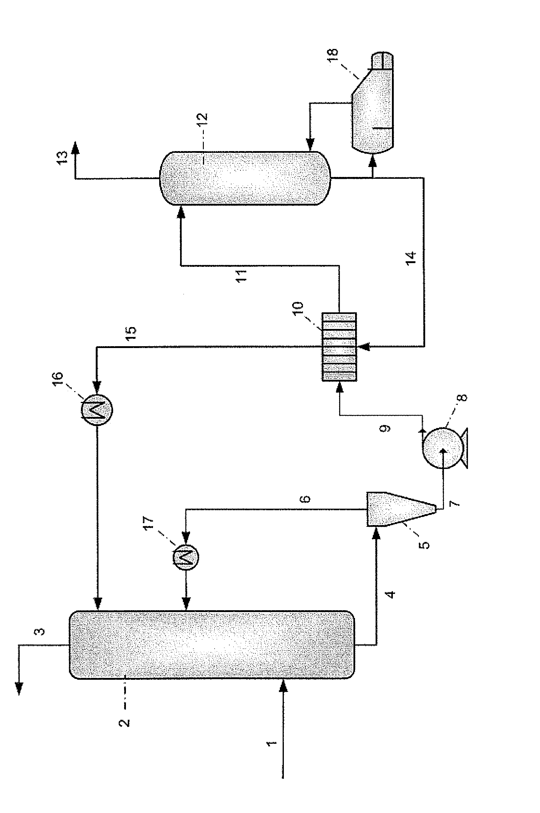
[0020]FIG. 1 is a scheme of a process for the removal of CO2 from a gas according to one embodiment of the invention. For the purpose of this description, a single reference number will be assigned to a line as well as stream carried in that line.

[0021]In step (a), the gas is contacted with an aqueous solution of one or more carbonate compounds in an absorber. The FIGURE shows a preferred embodiment wherein flue gas having a temperature of 40° C. and comprising about 8% of CO2 is led via line 1 to absorber 2 where it is contacted with an aqueous solution of one or more carbonate compounds. In the absorber, CO2 is reacted with the carbonate compounds to form bicarbonate compounds. The absorber is preferably operated at a temperature in the range of from 10 to 80° C., more preferably from 20 to 80° C. At least part of the bicar...


PUM

PropertyMeasurementUnit
Temperatureaaaaaaaaaa
Pressureaaaaaaaaaa

Abstract

A process for the removal of co2 from a gas comprising the steps of: (a) contacting the gas (1) in an absorber (2) with an aqueous solution of one or more carbonate compounds in the presence of an accelerator, thereby reacting at least part of the co2 to form a bicarbonate compound, under conditions such that at least a part of the bicarbonate compound formed precipitates, forming a bicarbonate slurry; (b) subjecting at least part of the bicarbonate slurry to a concentration step (5) to obtain an aqueous solution (6) and a concentrated bicarbonate slurry (7), wherein the concentrated bicarbonate slurry comprises from 20 to 80 wt % of bicarbonate compounds; (c) returning at least part of the aqueous solution to the absorber; (d) pressurising (8) the concentrated bicarbonate slurry, (e) transferring the pressurised concentrated bicarbonate slurry to a regenerator (12) and applying heat to obtain a co2-rich gas stream (13) and a regenerated carbonate stream (14).

Description

FIELD OF THE INVENTION[0001]The invention relates to a process for removal of carbon dioxide (CO2) from a gas.BACKGROUND OF THE INVENTION[0002]During the last decades there has been a substantial global increase in the amount of CO2 emission to the atmosphere. Emissions of CO2 into the atmosphere are thought to be harmful due to its “greenhouse gas” property, contributing to global warming. Following the Kyoto agreement, CO2 emission has to be reduced in order to prevent or counteract unwanted changes in climate. The largest sources of CO2 emission are combustion of fossil fuels, for example coal or natural gas, for electricity generation and the use of petroleum products as a transportation and heating fuel. These processes result in the production of gases comprising CO2. Thus, removal of at least part of the CO2 prior to emission of these gases into the atmosphere is desirable.[0003]Processes for removal of CO2 are known in the art.[0004]For example, in WO 2006 / 022885, a process ...

Claims


Application Information

Patent Timeline
IPC IPC(8): B01D53/62
CPCB01D53/1493B01D2251/606B01D53/1475Y02C10/06Y02C10/04Y02A50/20Y02C20/40
Inventor VAN STRAELEN, JIRI PETER THOMAS
Owner SHELL OIL CO
Why Eureka
Try Eureka