
Mgf2 optical thin film including amorphous silicon oxide binder, optical element provided with the same, and method for producing mgf2 optical thin film

a technology of optical thin film and silicon oxide, applied in the direction of nanotechnology, coatings, magnesium halides, etc., can solve the problems of insufficient refractive index of the film, insufficient environmental resistance, insufficient mechanical strength of the film and the etc., to achieve excellent environmental resistance (durability), improve mechanical strength of the film and adhesive force between the film and the base material, and improve environmental resistance.

Inactive Publication Date: 2011-05-26
NIKON CORP
View PDF13 Cites 24 Cited by
  • Summary
  • Abstract
  • Description
  • Claims
  • Application Information

AI Technical Summary

Benefits of technology

The solution enhances mechanical strength, adhesive force, and environmental resistance while achieving low reflectance across a wide spectral range, suitable for complex optical systems, including cameras and microscopes, with improved durability and optical performance.

Problems solved by technology

However, in the case of the film using MgF2 as described in International Publication No. 02 / 18982A1, the film strength and the adhesive force with respect to the base material are insufficient, although the refractive index of the optical thin film can be lowered to be not more than 1.30.
In the case of the films in which the film strength and the adhesive force with respect to the base material can be secured as described in Japanese Patent No. 3272111, Japanese Patent Application Laid-open No. 11-6902, Japanese Patent Application Laid-open No. 7-48527, Japanese Patent Application Laid-open No. 8-122501 and Japanese Patent Application Laid-open No. 2000-169133, the problem arises such that the refractive index of the film cannot be lowered sufficiently, and the environment resistance is insufficient.
There has been the problem such that it is not possible to obtain any optical thin film which is capable of sufficiently decreasing the refractive index and of securing the mechanical strength of the film, the adhesive force with respect to the base material, and the environment resistance.
However, in the case of the wet process, it is difficult to perform the multilayered coating.
On the contrary, if it is intended to lower the refractive index by providing a porous property to a film which is dense and which has a high refractive index, there is such a high possibility that the film itself may be collapsed (destroyed).
Therefore, such a procedure is extremely difficult to be executed.

Method used


Image

  • Mgf2 optical thin film including amorphous silicon oxide binder, optical element provided with the same, and method for producing mgf2 optical thin film
  • Mgf2 optical thin film including amorphous silicon oxide binder, optical element provided with the same, and method for producing mgf2 optical thin film
  • Mgf2 optical thin film including amorphous silicon oxide binder, optical element provided with the same, and method for producing mgf2 optical thin film

Examples


first embodiment

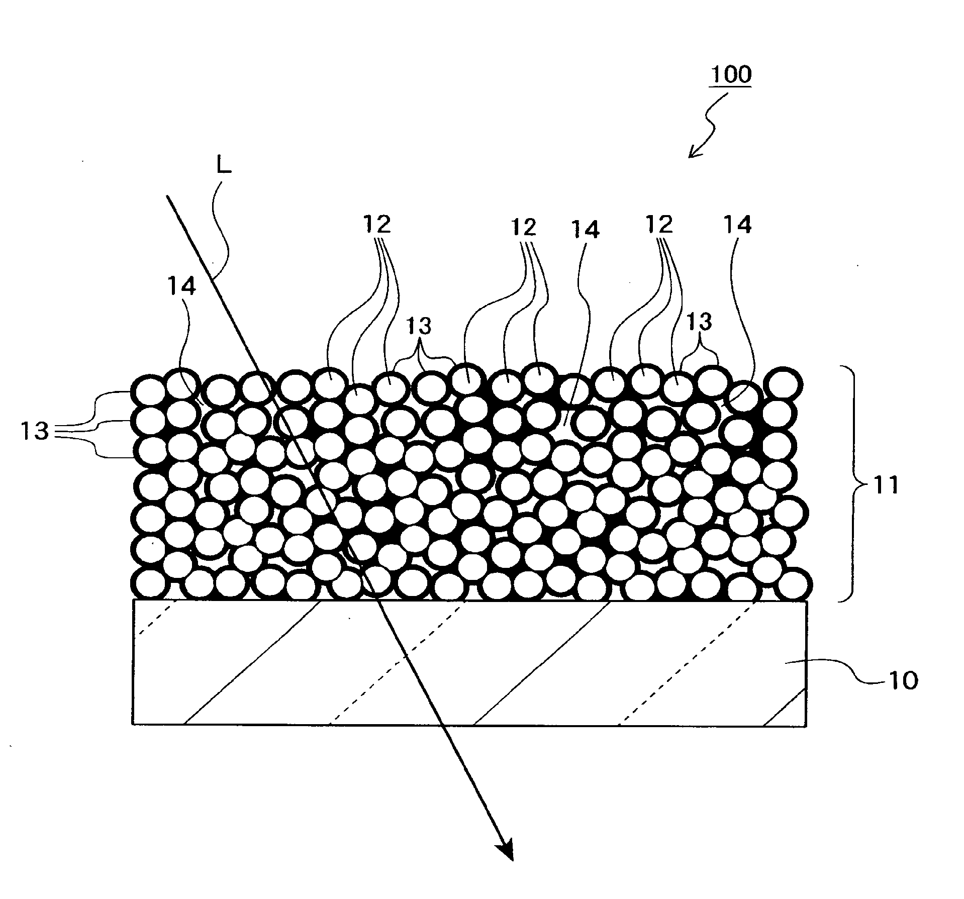
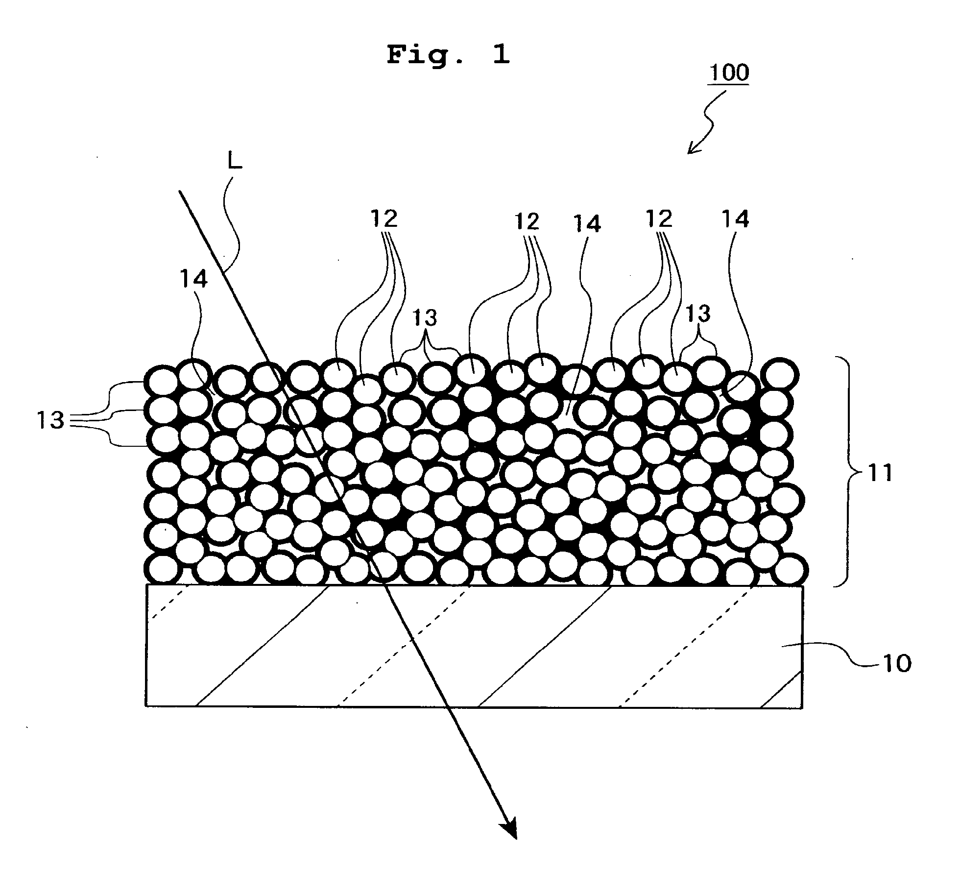
[0084]FIG. 1 shows an optical element in which an MgF2 optical thin film (MgF2—SiO2 film) of the first embodiment is formed. The optical element 100 includes a base material 10 and the MgF2 optical thin film 11 which is stacked on a flat optical surface of the base material 10. The base material 10 is formed of, for example, glass, plastic or the like having a refractive index of 1.4 to 2.1, and may be a plate member or a lens. The optical surface of the base material 10 may be formed to have a curved surface form.

[0085]The optical thin film 11 is an antireflection film which is stacked on at least one optical surface of the base material 10 onto which the light is radiated. In this embodiment, the optical thin film 11 is a singlelayered MgF2 antireflection film.

[0086]The optical thin film 11 includes MgF2 minute particles 12 and an amorphous silicon oxide-based binder 13. The connection is made by the amorphous silicon oxide-based binder 13 between a large number of the MgF2 minute...

examples 1 to 5

[0168]The hydrofluoric acid methanol solution was mixed with the magnesium acetate methanol solution so that the MgF2 concentration was 1%, and that the hydrofluoric acid / magnesium acetate ratio was 1.95 to prepare an MgF2 sol solution. Subsequently, the sol solution was subjected to the high temperature high pressure treatment at 140° C. for 24 hours. The average particle diameter of MgF2 minute particles contained in the treated MgF2 sol solution was measured by the electron microscopic observation, which was 20 nm. The sol solution was concentrated by using the rotary evaporator, followed by being diluted with 1-propanol to substitute 67% of the methanol solvent. The MgF2 sol solution was allowed to have an MgF2 concentration of 2.5%, with which a silica glass substrate having a thickness of 3 mm was spin-coated at 2,000 rpm to form a porous MgF2 film.

[0169]The substrate was dried at 70° C. for 1 hour, and then the temperature was returned to room temperature. An undiluted soluti...

examples 6 to 8

[0172]MgF2—SiO2 films were formed by the double coating method in the same manner as in Examples 1 to 5 except that MgF2 sol solutions were prepared by mixing the hydrofluoric acid methanol solution with the magnesium acetate methanol solution so that the MgF2 concentration was 1%, and the ratio of hydrofluoric acid / magnesium acetate was 1.98, 1.99, and 2.0. Characteristics of the obtained films were measured. Results are shown in Table 1.

[0173]When the results are compared with each other with respect to Example 1, the following fact is appreciated. That is, there is such a tendency that as the ratio of hydrofluoric acid / magnesium acetate is higher, the refractive index of the MgF2—SiO2 film becomes lower. In order to make the refractive index of the MgF2—SiO2 film as low as possible, it is appreciated that the ratio of hydrofluoric acid / magnesium acetate is preferably allowed to approach 2.0. However, if the ratio of hydrofluoric acid / magnesium acetate exceeds 2.0, then the gelati...


PUM

PropertyMeasurementUnit
particle diameteraaaaaaaaaa
refractive indexaaaaaaaaaa

Abstract

An MgF2 optical thin film is formed on an optical surface of a base material. The MgF2 optical thin film includes MgF2 particles and an amorphous silicon oxide-based binder which exists on the surfaces of the MgF2 particles and between the MgF2 particles. Owing to this amorphous silicon oxide-based binder, the optical thin film can have high mechanical strength and high adhesion to the base material, while having excellent environment resistance and a lower refractive index.

Description

CROSS-REFERENCE TO RELATED APPLICATION[0001]This application is a division of U.S. patent application Ser. No. 11 / 662,892 filed Mar. 15, 2007, which is a 371 of International Patent Application No. PCT / JP2005 / 017015 filed Sep. 15, 2005.TECHNICAL FIELD[0002]The present invention relates to a singlelayered or multilayered optical thin film formed of MgF2, a method for producing the same, an optical element having the MgF2 optical thin film, and an optical system for optical instruments such as cameras, microscopes, binoculars, and exposure apparatuses which is provided with the optical element.BACKGROUND ART[0003]Surfaces of individual lenses, which construct an optical system such as a camera lens and an objective lens of a microscope, are coated with an antireflection film in order to reduce the reflection. In general, the optical thin film such as the antireflection film is produced by the dry method (dry process), in which the vacuum vapor deposition method, the sputtering method,...

Claims


Application Information

Patent Timeline
Patent Type & Authority Applications(United States)
IPC IPC(8): G02B1/11B32B5/16B82Y20/00B82Y30/00B82Y40/00C01F5/28C03C17/34G02B1/113G02B1/115G02B1/14
CPCC03C17/007C03C2217/45C03C2217/475C03C2218/113G02B1/105Y10T428/258G02B1/113G02B2207/107G02B2207/109Y10T428/2495G02B1/111G02B1/14C01F5/28C03C17/22C03C17/25G02B1/11G02B1/116G02B1/118
Inventor ISHIZAWA, HITOSHINIISAKA, SHUNSUKEMURATA, TSUYOSHI
Owner NIKON CORP
Learn More