
CVD reactor with energy efficient thermal-radiation shield

Inactive Publication Date: 2011-06-02
WOONGJIN POLYSILICON
View PDF11 Cites 38 Cited by
  • Summary
  • Abstract
  • Description
  • Claims
  • Application Information

AI Technical Summary

Benefits of technology

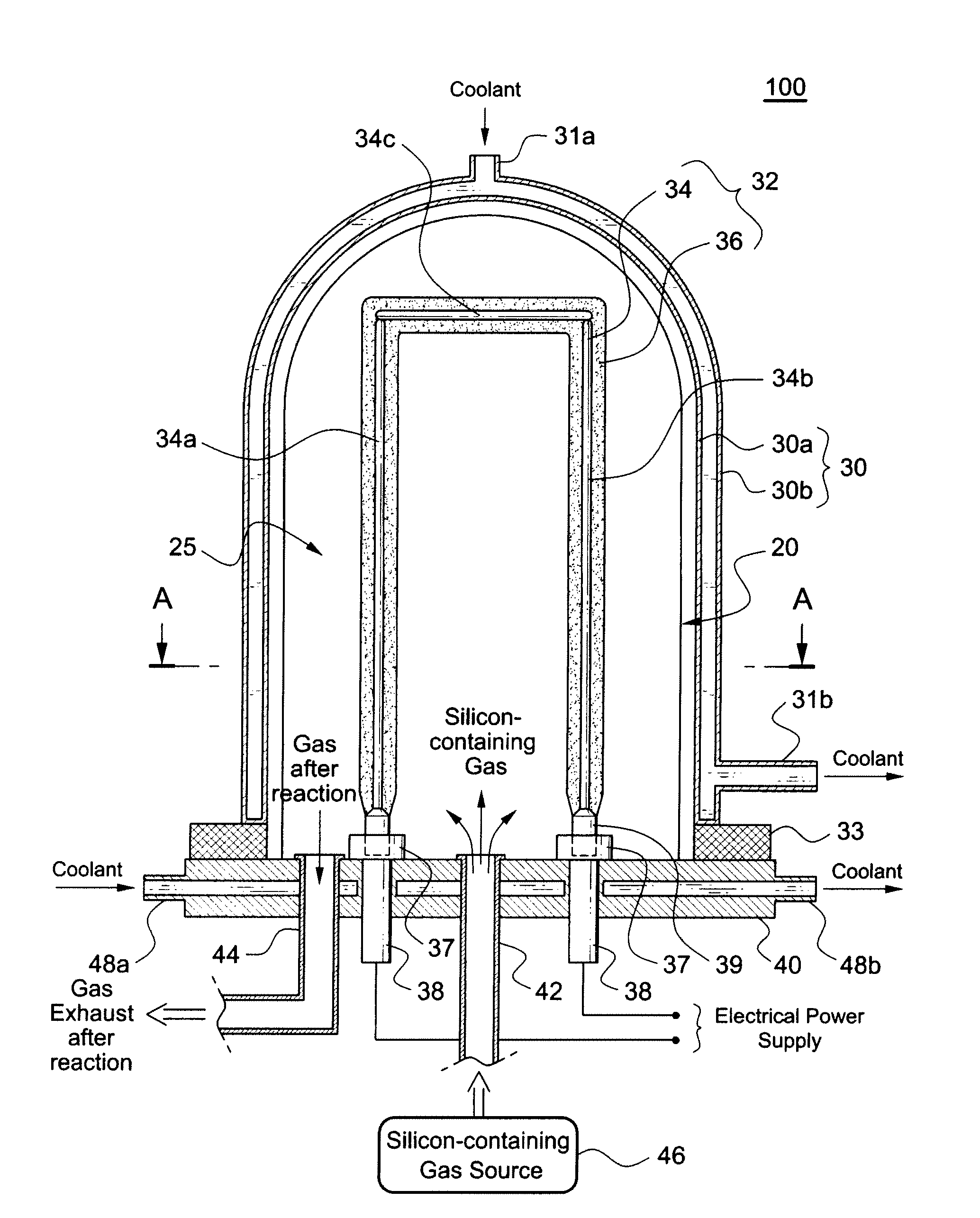
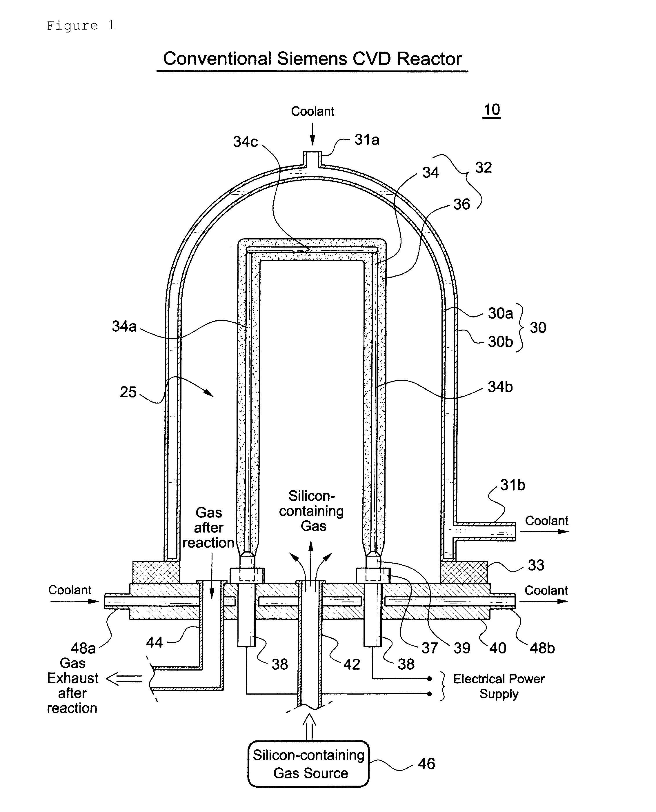
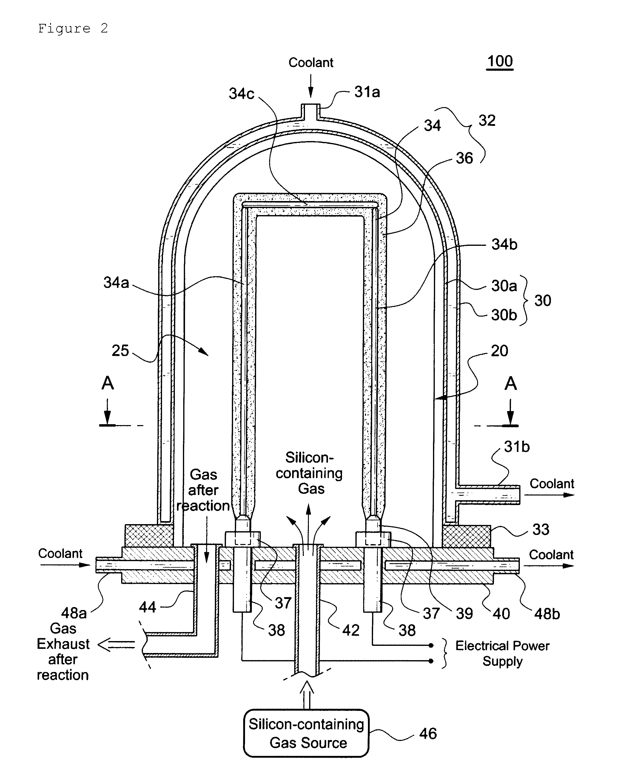
[0036]If radiation shields are installed between the polysilicon rod filament and the cooled wall in the Siemens CVD reactor as suggested by the present invention, the thermal loss from surface of the polysilicon in the reactor is reduced by blocking the thermal energy radiating from the heated filament rod toward the cooled wall. As a result, the net energy loss of the polysilicon rod is reduced, and the total electrical energy consumption of the CVD reactor can be reduced by the temperature control mechanism of the Siemens CVD reactor.
[0037]Additionally, by reducing the energy loss of the polysilicon rod, the temperature difference between the core and the surface of the polysilicon rod is reduced and the resulting tensile stress is reduced. Therefore, it is enabled to grow a polysilicon rod to a large diameter, increasing the productivity of the Siemens CVD reactor.

Problems solved by technology

But the Siemens process is also known as an energy intensive process and so the cost to produce semiconductor grade silicon using the Siemens process is relatively high.
The electrical energy-cost to produce polysilicon in a Siemens reactor typically runs between 65 and 200 kWh / kg resulting in electrical energy being the single largest cost factor.

Method used


Image

  • CVD reactor with energy efficient thermal-radiation shield
  • CVD reactor with energy efficient thermal-radiation shield
  • CVD reactor with energy efficient thermal-radiation shield

Examples


embodiment 1

[0085]A SiC-coated graphite thermal-radiation shield was placed between the heated rod filaments and the cooled wall of a Siemens CVD reactor. The 5 mm thick radiation shield covered the entire surface of the cooled wall but did not cover the surface of the base plate. The radiation shield was positioned with a 100 mm gap from the cooled wall. The spectral emissivity of the SiC coated graphite was considered to be 1.0. For a 115-mm diameter of polysilicon rod the total power consumption in the CVD reactor was 101 kW resulting in 24% electrical energy savings compared to the base-case. The polysilicon rod-core temperature was 1194° C. corresponding to a rod-core temperature decrease of 39° C. from the base-case.

embodiment 2

[0086]A perlite thermal-radiation shield was placed between the rod filaments and the cooled wall of a Siemens CVD reactor. The 100 mm thick radiation shield covered the entire surface of bell jar-shaped cooled wall, but did not cover the surface of the base plate. The radiation shield was positioned with a 5 mm gap from the cooled wall. The spectral emissivity of the perlite was considered to be 0.9 and the perlite thermal conductivity was 0.029 W / mK. For a 115 mm diameter of polysilicon rod, the total power consumption of the CVD reactor was 86 kW resulting in 35% electrical energy savings compared to the base-case. The polysilicon rod-core temperature was 1178° C. corresponding to a rod-core temperature decrease of 54° C. from the base-case.

embodiment 3

[0087]Three silicon thermal-radiation shields were placed between the rod filaments and the cooled wall of a Siemens CVD reactor. The silicon shields were configured as shown in FIG. 4. The 5 mm thick (ea) radiation shields covered the entire bell jar-shaped cooled wall, but did not cover the surface of the base plate. The radiation shields were positioned with a 5 mm gap from the cooled wall. The spectral emissivity of the silicon was considered to be 0.9. For a 115 mm diameter of polysilicon rod, the total power consumption of the CVD reactor was 52 kW resulting in 61% electrical energy savings compared to the base case. The polysilicon rod-core temperature was 1145° C. corresponding to a rod-core temperature decrease of 88° C. from the base-case.

[0088]The heat shield effects mentioned above, such as heat shield by virtue of high temperature emittance (>400° C.), heat shield by multiple layers of radiation shield, heat shield by low emissivity spectral emittance of shield material...


PUM

PropertyMeasurementUnit
Temperatureaaaaaaaaaa
Poweraaaaaaaaaa
Temperatureaaaaaaaaaa

Abstract

A Siemens type CVD reactor device is provided. One or more radiation shields are disposed between a rod filament and a cooled wall in the reactor. The radiation shield absorbs radiant heat emanating from the heated polysilicon rod during the CVD process, gets heated above 400° C., re-radiate the absorbed heat toward both of the polysilicon rod and the cooled wall, so as to provide thermal shielding effect to the cooled wall. The net energy loss of the polysilicon rod is reduced as much as the amount of energy emitted toward the polysilicon rod from the radiation shield, such that considerable amount of electrical energy of the CVD reactor is reduced and saved. The energy reduction rate goes up much higher if using multiple layered radiation shields, low shielding emissivity, and low thermal conductivity together. The purity of the manufactured polysilicon can be maintained by using thermal shielding material that is stable in a high temperature such as graphite, silicon carbide-coated graphite, and silicon.

Description

TECHNICAL FIELD[0001]The invention relates to an improvement of a CVD reactor and more specifically to an art to improve the productivity of polysilicon rods as well as to lower the costs for producing them by reducing electrical energy loss in Siemens CVD reactors.BACKGROUND ART[0002]Polycrystalline silicon, or polysilicon, is a critical raw material for the electronics industry. It is the starting material for production of single and multi-crystal silicon ingots for the semiconductor and photovoltaic industries. Semiconductor grade polysilicon contains electronically-active impurities in the parts per billion or parts per trillion ranges.[0003]Generally, polysilicon rods are made by the pyrolytic decomposition of a gaseous silicon compound, such as mono-silane or a chlorosilane (e.g., trichlorosilane) on a rod-shaped, red-heated starter rod or filament made preferably from a silicon seed rod or, alternatively, from a high-melting point metal having good electrical conductivity su...

Claims


Application Information

Patent Timeline
IPC IPC(8): C23C16/00
CPCC01B33/035C23C16/46C23C16/4418C23C16/24C23C16/44C23C16/22
Inventor LEE, JONG GYUKIM, JONG ROCKLEE, SANG WOOWINTERTON, LYLE C.
Owner WOONGJIN POLYSILICON
Learn More