Polarized xenon gas concentration method, polarized xenon gas manufacturing supply device, and MRI system

a technology manufacturing supply device, which is applied in the direction of magnetic variable regulation, separation processes, instruments, etc., can solve the problems of reducing the polarization rate, unable to produce continuous polarized xenon gas, and limited use of polarized xenon gas, etc., and achieves high polarization rate and high sensitivity. , the effect of high polarization ra

Inactive Publication Date: 2011-06-02
OSAKA UNIV
View PDF13 Cites 9 Cited by
  • Summary
  • Abstract
  • Description
  • Claims
  • Application Information

AI Technical Summary

Benefits of technology

[0015]The polarized xenon gas concentration method of the present invention is capable of concentrating xenon gas having a high polarization rate at a high concentration.
[0016]The polarized xenon gas manufacturing supply device of the present invention can continuously supply xenon gas with a high polarization rate at a high concentration.
[0017]The MRI system of the present invention allows MRI measurement to be performed continuously with high sensitivity.

Problems solved by technology

However, this method has a drawback in that the polarization rate decreases in the process of solidifying and volatilizing the xenon.
This makes the continuous production of polarized xenon gas impossible; therefore, its use is limited to NMR or MRI experiments conducted in a batch mode.
However, although the device disclosed in Patent Literature 1 succeeded in obtaining a higher concentration of polarized gas by transmitting only the diluent gas and the polarized gas is concentrated to approximately twofold in xenon concentration, the polarization rate of xenon gas is reduced to ½. Therefore, a reduction in the polarization rate is serious and the total sensitivity (polarization rate×concentration) is not improved as a whole.

Method used


Image

  • Polarized xenon gas concentration method, polarized xenon gas manufacturing supply device, and MRI system
  • Polarized xenon gas concentration method, polarized xenon gas manufacturing supply device, and MRI system
  • Polarized xenon gas concentration method, polarized xenon gas manufacturing supply device, and MRI system

Examples


examples

[0059]The present invention is explained in detail below with reference to Examples. However, the scope of the invention is not limited to the Examples described below.

example a

Using Isobutene as the Diluent Gas

Relationship Between Diluent Gas and Sensitivity

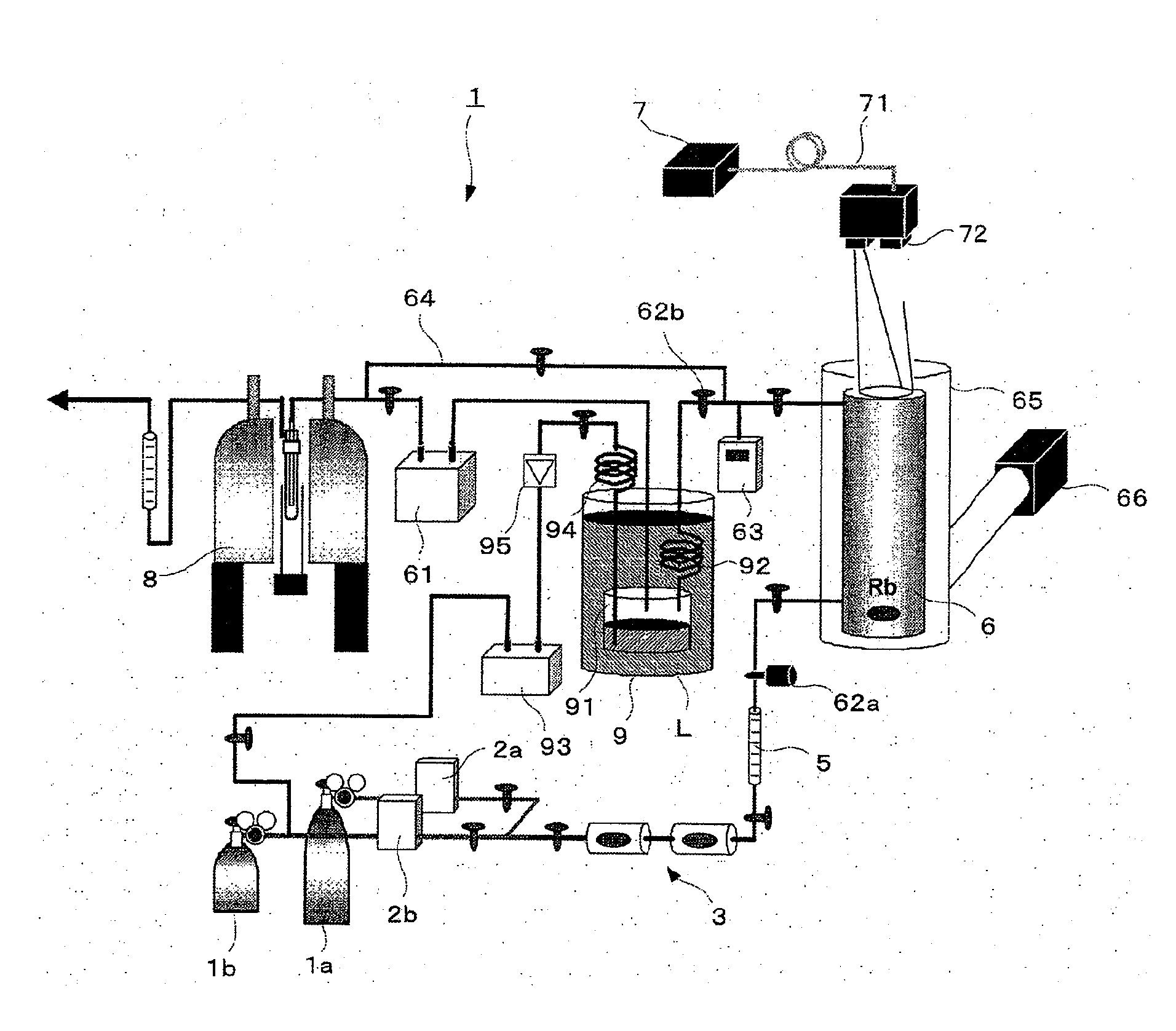
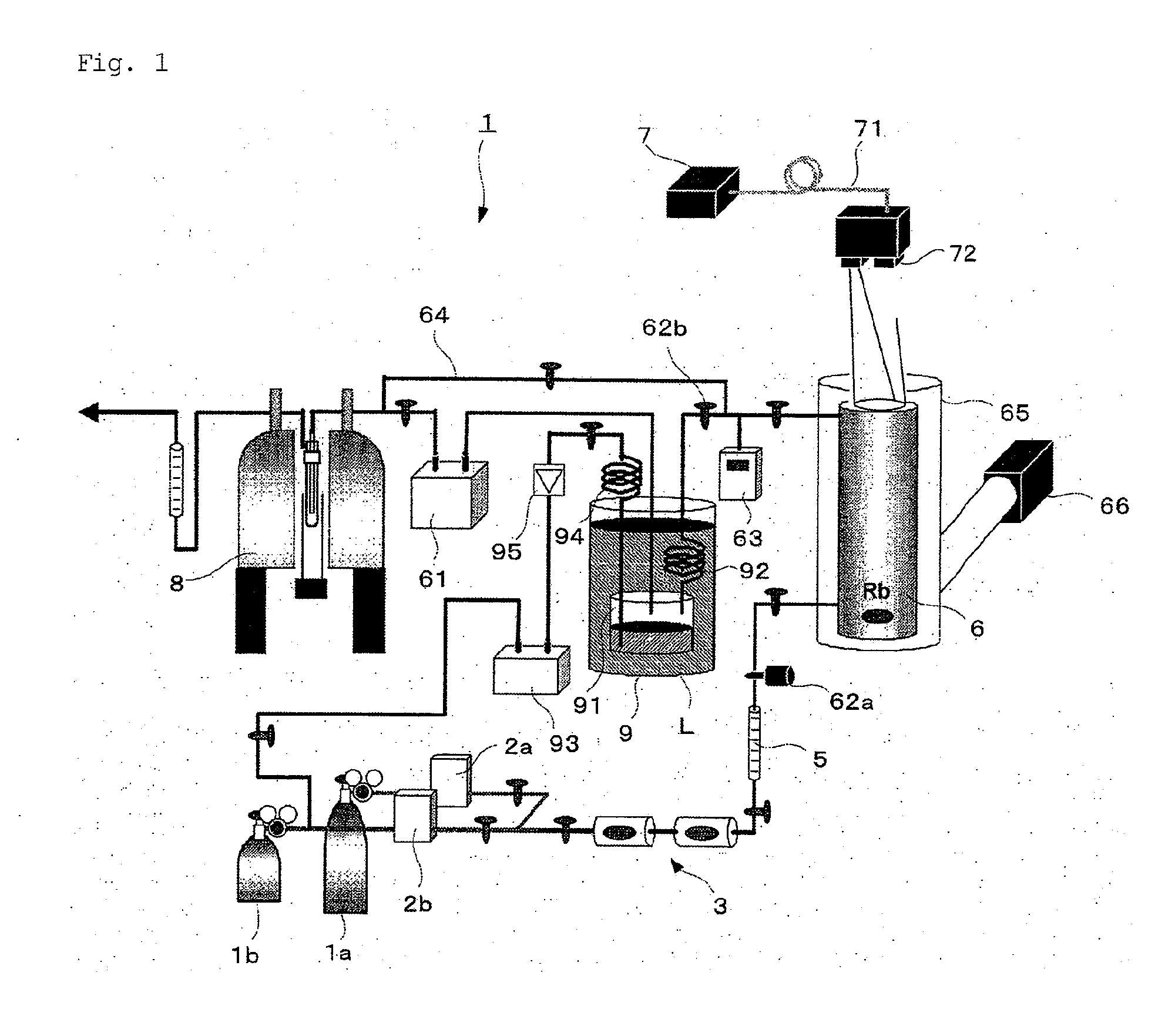
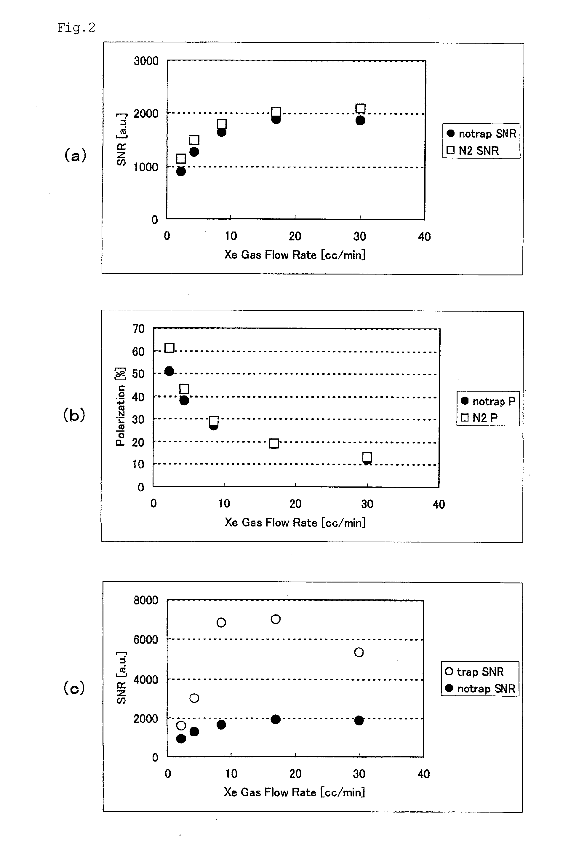
[0060]A cylindrical polarization cell (diameter: 60 mm, length: 30 cm) storing rubidium as an alkali metal was placed in a 110° C. high-temperature bath. A mixture of a xenon gas and a diluent gas was introduced to the polarization cell. After the inside pressure of the polarization cell was set to 0.15 atm, the cell was emitted for 20 minutes with the circularly polarized light which was obtained by converting a laser light with wavelength of 795 nm and output of 90 W emitted from the excitation light source. While feeding the gas in the cell into an NMR sample tube, NMR signals were measured to evaluate the signal-to-noise ratio (SNR). A similar measurement was conducted using a standard sample for SNR measurement. Based on the ratio between the SNR of the gas in the cell and that of a standard sample, the polarization rate PXe of 129Xe was obtained using the formula below.

PXe=(S / N)p(S / N)e·(Xe%)e(Xe%...

example b

Using Propene as the Diluent Gas

[0069]Table 3 shows the results of Example 2 conducted using propene (C3H6, H3CCH═CH2, boiling point: −47.7° C., melting point: −185° C.) as the diluent gas instead of nitrogen. The experiments were conducted in the same manner as in Example 1 except that the polarization cell had a diameter of 60 mm with a length of 20 cm and that the laser power used for excitation was 90 W and the temperature of the cryostat used for the condensation of propene was −114° C. Because Example 2 differed in the cell size and laser power from those in Comparative Examples 1 and 2, the comparative experiments were re-conducted under the same conditions as in Example 2 and these experiments were defined as Comparative Examples 3 and 4.

[0070]The graph in FIG. 4 shows the signal-to-noise ratio (SNR) in Table 3. In FIG. 4, the white dots (◯) indicate the results of Example 2, the black dots () indicate the results of Comparative Example 3, and the squares (▪) indicate the r...


PUM

PropertyMeasurementUnit
natural abundanceaaaaaaaaaa
boiling pointaaaaaaaaaa

Abstract

The present invention relates to a polarized xenon gas manufacturing supply device that is provided with a polarization cell 6 that produces a polarized xenon gas by polarizing a mixture of xenon gas and a diluent gas that consists primarily of a high-boiling-point gas that has a boiling point higher than that of the xenon gas, and a condenser (9) that cools the mixed gas discharged from the polarization cell (6) and condenses and separates the high-boiling-point gas by using the difference in boiling points between the xenon gas and the high-boiling-point gas, wherein the supply device is constructed so as to re-vaporize the condensed liquid of the high-boiling-point gas produced by the condenser (9) and introduce it to the polarization cell (6). This polarized xenon gas manufacturing supply device makes it possible to continuously manufacture and supply highly polarized and highly concentrated xenon gas.

Description

TECHNICAL FIELD[0001]The present invention relates to a polarized xenon gas concentration method, a polarized xenon gas manufacturing supply device, and an MRI system.BACKGROUND ART[0002]A polarized xenon gas can be produced by, for example, an optical-pumping method that uses rubidium or a like alkali metal. The polarized xenon gas is suitably used for NMR (nuclear magnetic resonance) devices, MRI (magnetic resonance imaging) devices and the like. In order to obtain a highly polarized xenon gas, a diluent gas composed of nitrogen, helium or like inert gas is usually added to a xenon gas during its production process. By separating the resulting polarized xenon gas from the diluent gas and concentrating it, a highly concentrated polarized xenon gas can be obtained.[0003]Using liquid nitrogen to solidify a polarized xenon gas has been proposed as a method for concentrating the polarized xenon gas by separation of a diluent gas. However, this method has a drawback in that the polariza...

Claims


Application Information

Patent Timeline
Patent Type & Authority Applications(United States)
IPC IPC(8): G01R33/28F25J3/00F25B21/00F25J1/00
CPCG01R33/282B01D7/02
Inventor FUJIWARA, HIDEAKIIMAI, HIROHIKOIGUCHI, SATOSHIYOSHIMURA, HIRONOBUKIMURA, ATSUOMI
Owner OSAKA UNIV
Why Eureka
Try Eureka