Color filter substrate and liquid crystal display device

a color filter substrate and liquid crystal display technology, applied in the direction of optics, instruments, optical elements, etc., can solve the problems of deteriorating the oblique visibility of the liquid crystal display device, affecting the physical properties of the color filter, and affecting the luminosity of green, etc., to achieve excellent oblique visibility, high contrast, and excellent oblique visibility

Inactive Publication Date: 2011-06-23
TOPPAN PRINTING CO LTD
View PDF4 Cites 8 Cited by
  • Summary
  • Abstract
  • Description
  • Claims
  • Application Information

AI Technical Summary

Benefits of technology

[0011]Objects of the present invention are to provide a color filter substrate having a green pixel of small retardation while securing not only optimal green but also high luminosity of green and to provide a liquid crystal display device having the aforementioned color filter substrate incorporated therein and exhibiting high contrast and excellent oblique visibility when displaying the darkened or OFF state.

Problems solved by technology

Even if optical designing is elaborated on a liquid crystal display device as a whole, a small degree of retardation (for example, +10 nm or so) is inevitably left uncorrected in the color layers of color filter, thereby more likely deteriorating the oblique visibility of the liquid crystal display device.
Especially in the case of green pixel which is high in luminosity factor to the eyes of viewers, the magnitude of retardation may become a problem.
The methods described above however are accompanied with a problem that when it is tried to control the retardation of the pixels, various characteristics including the physical properties of the color filter are caused to change.
The reason is that when a side chain having a planar structural group is introduced into a high polymer acting as a pigment carrier in a color film, the density, mechanical strength and chemical resistance of the color film may be caused to change or the etching characteristics of the color film may be caused to change in a system of creating a pattern by means of photolithography, thereby raising various problems in the manufacture of the color filter.
Especially, in the case of a green pixel which is very important in terms of luminosity factor, it has been considered difficult to minimize the retardation while securing not only the optimal color as green but also high luminosity of green.

Method used


Image

  • Color filter substrate and liquid crystal display device
  • Color filter substrate and liquid crystal display device
  • Color filter substrate and liquid crystal display device

Examples


first embodiment

[0033]The green pixel to be employed in a color filter according to the present invention is formed of a color composition containing a pigment carrier made of at least a transparent resin or a mixture thereof, halogenated zinc phthalocyanine-based green pigment, and at least one kind of yellow pigment. This green pixel is also designed such that the sum of the products of: (birefringence of a sample color film of each of pigments)×(weight ratio of each pigment) would be confined to no more than 0.006.

[0034]In a color filter including green pixel formed of the aforementioned color composition, it is possible to carry out the retardation control by adjusting the absolute value of retardation in thickness direction (Rth) of the green pixel, which can be represented by the following equation, to no more than 2 nm.

Rth={(Nx+Ny / 2−Nz) / 2−Nz}×d

[0035]wherein Nx is a refractive index in x-direction in the plane of green pixel; Ny is a refractive index in y-direction in the plane of green pixe...

second embodiment

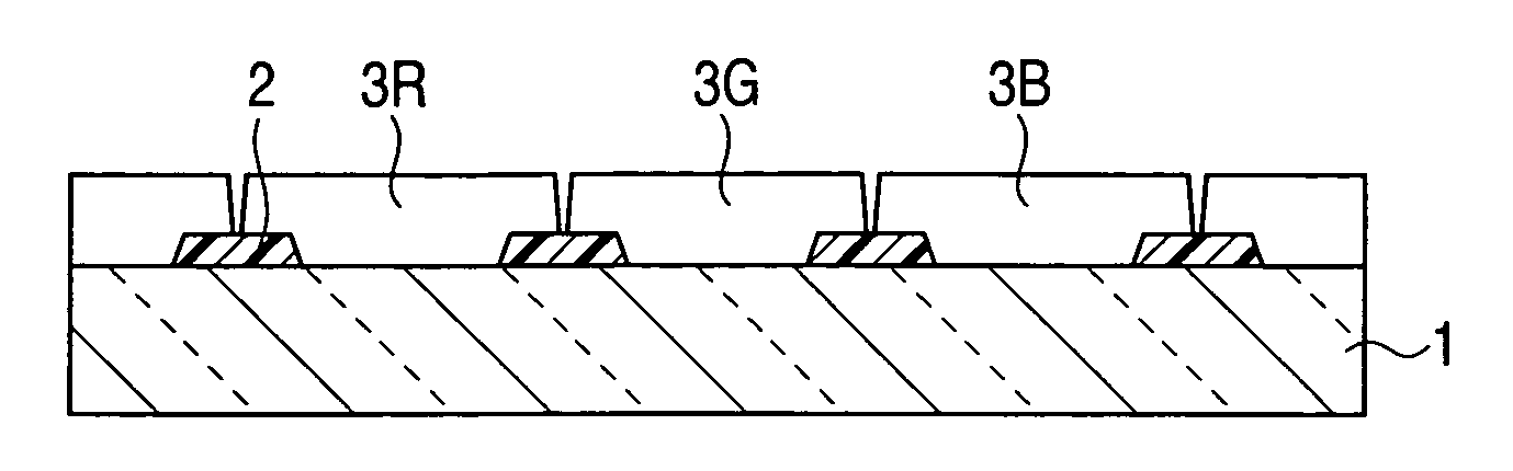
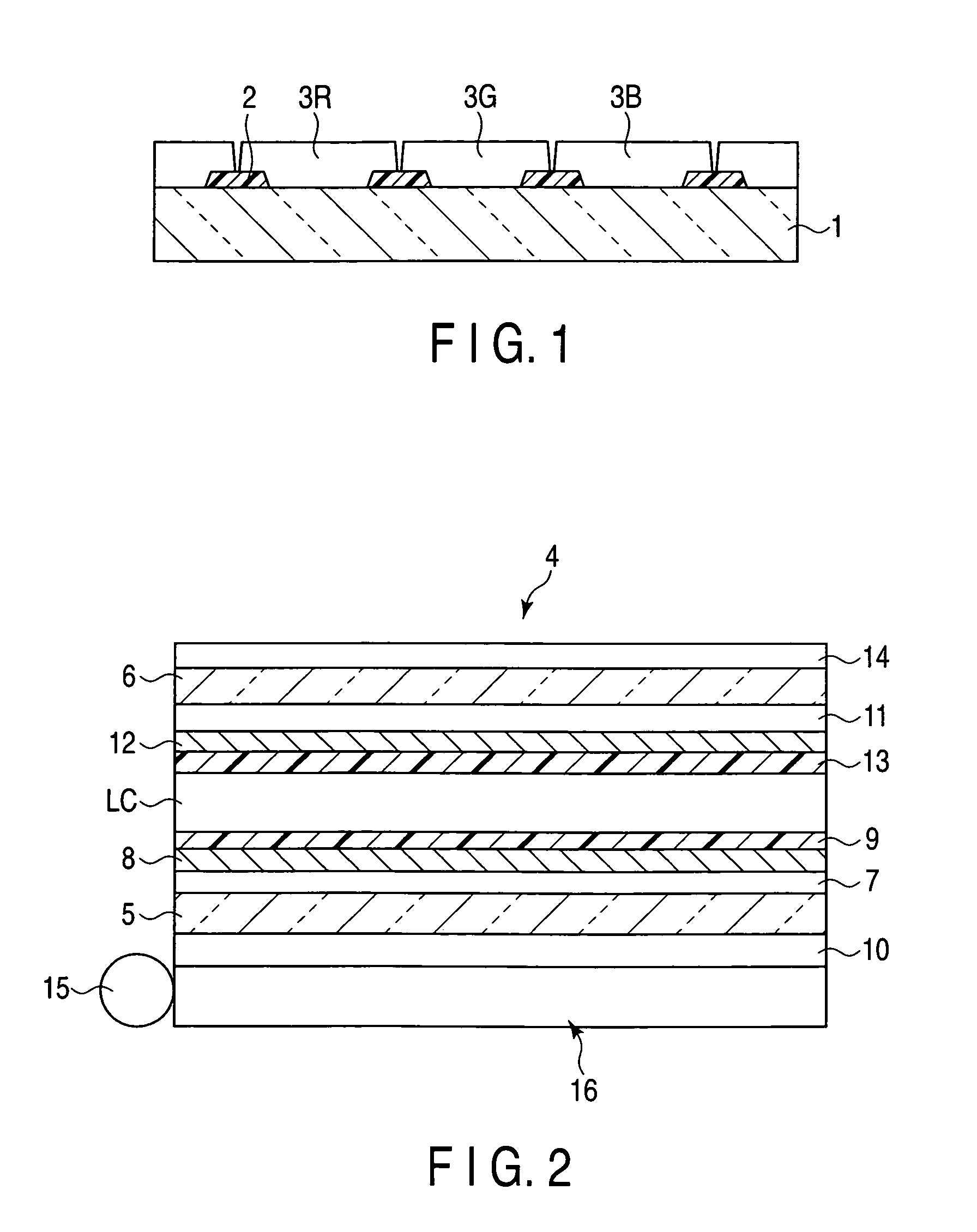
[0136]FIG. 2 is a cross-sectional view schematically illustrating the liquid crystal display device according to the present invention.

[0137]The liquid crystal display device 4 shown in FIG. 2 illustrates a typical example of a TFT-drive liquid crystal display device which is provided with a pair of transparent substrates arranged face to face with a gap interposed therebetween and filled with a liquid crystal (LC).

[0138]In the second embodiment of the present invention, various kinds of liquid crystal (LC) can be employed such as twisted nematic (TN), super twisted nematic (STN), in-plane switching (IPS), vertical alignment (VA), optically compensated birefringence (OCB), etc. It is also possible to employ a liquid crystal-driving method called fringe field switching (FFS) wherein the transparent electrode (pixel electrode) disposed on the surface of color filter or on the substrate side having a TFT formed thereon is formed into a comb-like or stripe-like configuration.

[0139]On th...

example 1

[0147](Pigment-Manufacturing Example 1)

[0148]46 parts of zinc phthalocyanine was dissolved in a molten salt heated to 200° C. and consisting of 356 parts of aluminum chloride and 6 parts of sodium chloride. Then, the resultant solution was cooled to 130° C. and stirred for one hour. Thereafter, the reaction temperature was raised to 180° C. and bromine was added drop-wise at a rate of 10 parts per hour to this reaction mixture taking 10 hours. Then, chlorine was added at a rate of 0.8 parts per hour to this reaction mixture taking 5 hours.

[0149]The resultant reaction mixture was gradually poured into 3200 parts of water and then subjected to filtration and water washing to obtain 107.8 parts of crude zinc phthalocyanine halide pigment. An average number of bromine atoms included in one molecule of this crude zinc phthalocyanine halide pigment was 14.1 and an average number of chlorine atoms included in one molecule of this crude zinc phthalocyanine halide pigment was 1.9.

[0150]Then,...


PUM

PropertyMeasurementUnit
particle diameter d50aaaaaaaaaa
transparentaaaaaaaaaa
luminosityaaaaaaaaaa

Abstract

Disclosed is a color filter substrate provided with a transparent substrate, and a plurality of color pixels including a green pixel and formed on the transparent substrate. The green pixel contains halogenated zinc phthalocyanine-based green pigment and at least one kind of yellow pigment and satisfies prescribed three conditions, and absolute value of retardation in thickness direction (Rth) of the green pixel is confined to no more than 2 nm.

Description

CROSS-REFERENCE TO RELATED APPLICATIONS[0001]This application is based upon and claims the benefit of priority from prior Japanese Patent Application No. 2009-291416, filed Dec. 22, 2009, the entire contents of which are incorporated herein by reference.BACKGROUND OF THE INVENTION[0002]1. Field of the Invention[0003]This invention relates to a color filter substrate to be employed in a liquid crystal display device, and to a liquid crystal display device which is provided with this color filter substrate.[0004]2. Description of the Related Art[0005]In recent years, slim display devices such as a liquid crystal display device are increasingly demanded to enhance the picture image and power-saving thereof and to lower the manufacturing cost thereof. Especially, in the case of an oversize television or a high picture quality monitor, where the display contrast thereof is not less than 2000, they are now demanded to exhibit not only a high front contrast but also a very high level of di...

Claims


Application Information

Patent Timeline
Patent Type & Authority Applications(United States)
IPC IPC(8): G02F1/1335G02B5/22
CPCG02B5/201
Inventor SHIMIZU, MIEIKEDA, TAKESHIHAGIWARA, HIDESATOMINATO, KOICHI
Owner TOPPAN PRINTING CO LTD
Why Eureka
Try Eureka