Method of manufacturing film for film capacitor and film for film capacitor

a manufacturing method and film capacitor technology, applied in capacitor manufacture, fixed capacitor details, instruments, etc., can solve the problems of poor heat resistance of film capacitors, poor unsolved problems relating to weight reduction and cost efficiency, etc., to achieve excellent heat resistance, voltage proof, and slidability.

Active Publication Date: 2011-06-23
SHIN-ETSU POLYMER CO LTD
View PDF9 Cites 7 Cited by
  • Summary
  • Abstract
  • Description
  • Claims
  • Application Information

AI Technical Summary

Benefits of technology

[0043]According to the present invention, there can be provided a method of manufacturing a film for film capacitors, which is capable of readily and reliably manufacturing a film for film capacitors, having excellent heat resistance, voltage proof, and slidability or the like, in which occurrences of streaks or wrinkles and die lines are restrained, by melt extruding a simple polyetherimide resin as the molding material at starting step of extrusion operation of the extruder in an inert gas atmosphere obtained by replacing air in the extruder with an inert gas, and then, switching the molding material to a resin composition obtained by adding 1.0 to 30.0 parts by mass of a fluorine resin to 100 parts by mass of a polyetherimide resin to mold the film for film capacitors.

Problems solved by technology

A film for film capacitors, which is currently practically available, is a film obtained from four kinds of resins such as a PP resin, a PET resin, a PPS resin, and a PEN resin, and films obtained from other resins are hardly used, since there is a problem associated with cost efficiency or processing adaptability.
However, the film for film capacitors, made of the PP resin and the PET resin, show poor heat resistance, because the use temperature of the PP resin is 105 degrees centigrade or less and the use temperature of the PET resin is 125 degrees centigrade or less.
Therefore, for example, if they are used as films for film capacitors of a hybrid vehicle which requires heat resistance of 150 degrees centigrade or more, it is inevitable to employ: (1) a method of installing large-sized cooling equipment without paying attention to a request for weight reduction; and (2) a method of installing a capacitor at, e.g., a driver's seat side which is distant from an engine room as a heat source without paying attention to space efficiency, and so problems associated with weight reduction and cost efficiency still remain unsolved.
However, its applicability is limited, since it has low dielectric breakdown voltage and poor voltage proof.
However, its applicability is limited, since it has large dielectric loss and large temperature dependency of dielectric tangent.
However, the film made of the polyetherimide resin lacks in film lubricity (or slidability), and therefore, sometimes causes troubles such as interruption of winding operation or slitting operation of the film, appearance of wrinkles on the film, and sticking of the film to guide rolls, etc., during manufacturing operation of the film.
In addition, if film blocking may occur and then the wound film is released during capacity assembling, the film may break and cause a problem in the assembling.
However, as described in Japanese Patent Application Laid-open No. 2007-300126, in a case where the film surface made of the polyetherimide resin is formed by applying plasma treatment in a fluorination atmosphere, a plasma treatment device is needed, and there are problems of higher manufacturing cost as well as complicated manufacturing.
However, in a case where a film for film capacitors is molded by a melt extrusion molding technique using a resin composition obtained by adding a fluorine resin to a polyetherimide resin as a molding material, when the resin composition melted and kneaded in an extruder is extruded from a T-die, the polyetherimide resin and the fluorine resin are separated each other, and the polyetherimide resin unevenly adheres to a flow passage face of a lip portion of the T-die.
A difference in stress generated between a streaked portion and a streak-free portion causes wrinkles and in turn, there occurs a problem that a value of the film for film capacitors is extremely degraded.

Method used


Image

  • Method of manufacturing film for film capacitor and film for film capacitor
  • Method of manufacturing film for film capacitor and film for film capacitor
  • Method of manufacturing film for film capacitor and film for film capacitor

Examples


examples

[0088]Hereinafter, a method of manufacturing films for film capacitors and a film for film capacitors, according to the present invention, will be described referring to examples and comparative examples. The method of manufacturing films for film capacitors and the film for film capacitors, according to the present invention, are not limitative to these examples that follow.

[0089]Polyetherimide resin: Trade name “Ultem 1010-1000”, Available from SABIC Innovative Plastics Japan, Glass transition point of 223 degrees centigrade.

[0090]Fluorine resin: Trade name “Fluon PFA P-62×P”, Available from Asahi Glass Co., Ltd, PFA resin, Melt viscosity of 11,100 poises at 360 degrees centigrade;

[0091]Fluorine-based surfactant: Trade name “KFBS”, Available from Mitsubishi Materials Electronic Chemicals Co., Ltd, Potassium Nonafluorobutane sulfonate (C4F9SO3K)

[0092]FIG. 4 is a tabular view showing a relationship of mixing composition, amount of nitrogen supply, simple polyetherimide resin extrusi...


PUM

PropertyMeasurementUnit
thicknessaaaaaaaaaa
roughnessaaaaaaaaaa
temperatureaaaaaaaaaa

Abstract

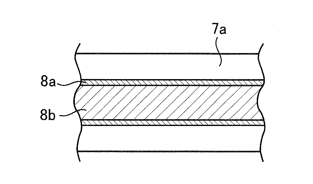
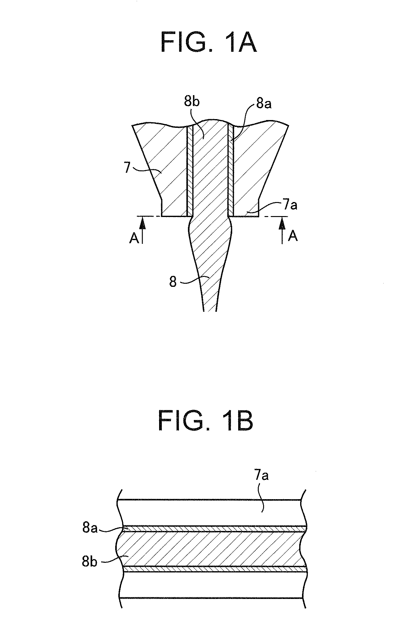
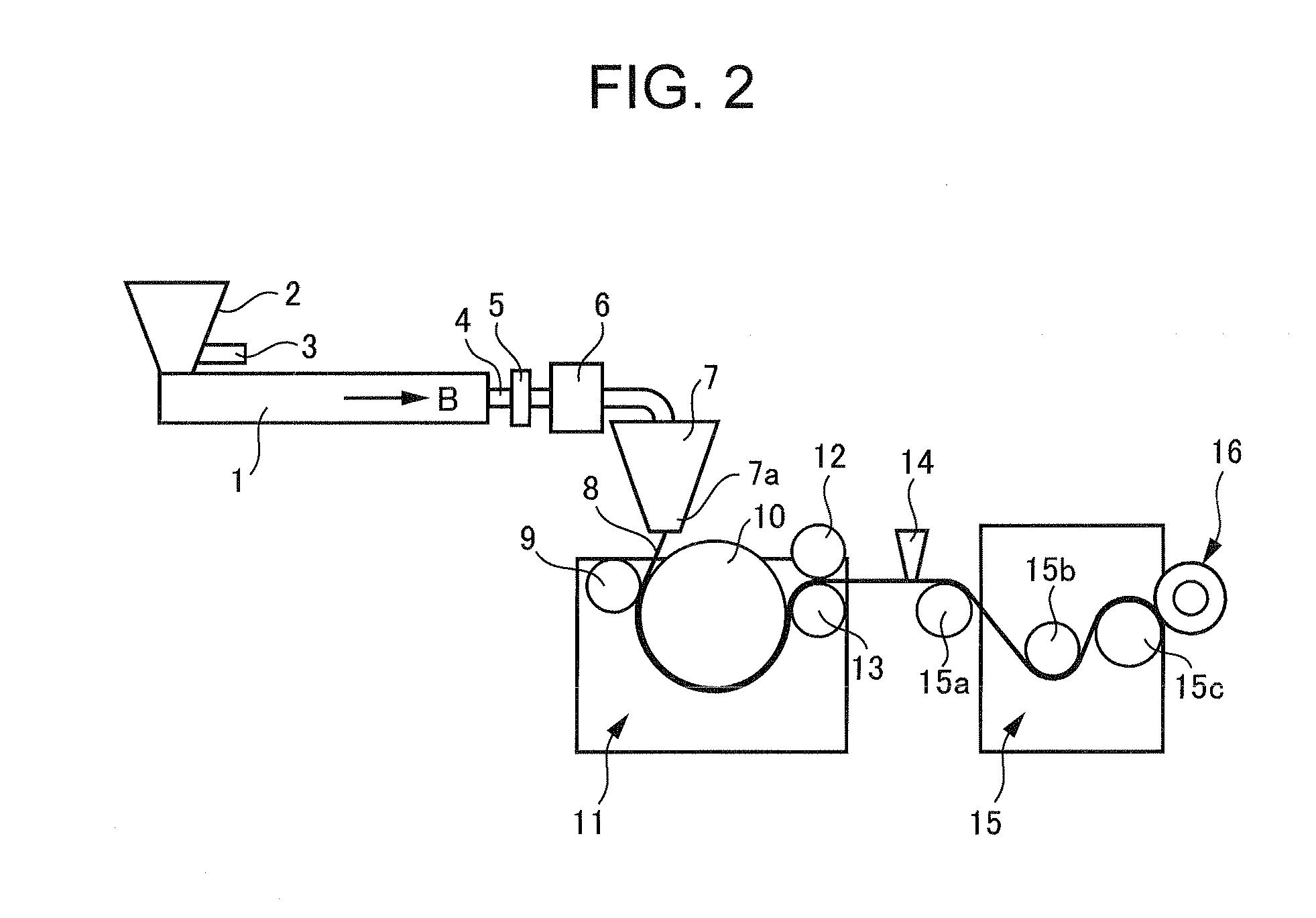
When extrusion of a molten resin by means of an extruder is started, a simple polyetherimide resin is melt extruded from a lip portion 7a of a T-die 7, and a film of the simple polyetherimide resin is molded. The molding material is then switched to a resin composition including the polyetherimide resin and a fluorine resin and then a film of the resin composition is continuously extruded and molded from the T-die 7. Having been covered with a very thin film 8a of the simple polyetherimide resin, on a flow passage face of the lip portion 7a of the T-die 7, a resin composition layer 8b including a polyetherimide resin and a fluorine resin, which has affinity with the film 8a, is then formed at a center part.

Description

CROSS-REFERENCE TO RELATED APPLICATIONS[0001]This application is based on and claims a priority from the prior Japanese patent Application No. 2009-285930 filed on Dec. 17, 2009, the entire contents of which are incorporated herein by reference.BACKGROUND OF THE INVENTION[0002]1. Field of the Invention[0003]The present invention relates to a method of manufacturing a film for film capacitors and the film for the film capacitors.[0004]2. Description of the Related Art[0005]Capacitors can be classified into three kinds of capacitors, i.e., film capacitors, ceramic capacitors, and aluminum-electrolytic capacitors, according to kinds of dielectrics. Among these three kinds of capacitors, a film capacitor is superior to the other capacitors in terms of its characteristics that it is high in insulation property, is small in dielectric loss, and is small in characteristic change relative to a temperature or a frequency. This matter is described in Norifumi KANOU, “Technical Trend for Capac...

Claims


Application Information

Patent Timeline
Patent Type & Authority Applications(United States)
IPC IPC(8): B32B5/00B29C47/14B29C48/08B29C48/305B29C48/92
CPCB29C47/0021Y10T428/24355B29C47/14B29C47/8845B29C47/92B29C2947/92152B29C2947/922B29C2947/92228B29C2947/92238B29C2947/92285B29C2947/92342B29C2947/92438B29C2947/92447B29C2947/9259B29C2947/92923B29K2079/085B29K2105/256C08J5/18C08J2379/08C08L79/08H01G4/18H01G13/00B29C47/0004B29C47/1072B29C47/10B29C48/9155B29C48/285B29C48/08B29C48/92B29C48/022B29C48/295B29C48/305B29C48/914B29C2948/922B29C2948/9259B29C2948/92152B29C2948/92228B29C2948/92238B29C2948/92285B29C2948/92342B29C2948/92438B29C2948/92447B29C2948/92923
Inventor OTE, MICHIMASAGONDA, TAKASHIISHIDA, JUNYATAKIZAWA, KENROSUZUKI, KAZUHIROMORIOKA, YUZO
Owner SHIN-ETSU POLYMER CO LTD
Why Eureka
Try Eureka