Method to evaluate plants and soils to optimize conditions for phytoremediation

a technology of phytoremediation and plant soil, applied in the field of environmental engineering, can solve the problems of wasting decades in the removal of contaminant, and achieve the effects of saving financial resources, low installation and maintenance costs, and less cos

Inactive Publication Date: 2011-06-23
BUCHANAN CATHERINE LYNN
View PDF0 Cites 11 Cited by
  • Summary
  • Abstract
  • Description
  • Claims
  • Application Information

AI Technical Summary

Benefits of technology

[0005]The advantages of utilizing plants for remediation of contaminated soils are becoming recognized. For a community wishing to save financial resources, phytoremediation is less costly than conventional methods due to its low installation and maintenance costs (Rock, 1996). Phytoremediation may also establish wildlife habitat and can add to the aesthetics and recreational benefits of the community (Rock, 1996). Additional advantages of phytoremediation are that 1) plants can stabilize and / or remove contaminants, 2) contaminants can be transferred to a treatment or disposal site with relative ease, and 3) diversity and productivity of the soil ecosystem may be maintained (Khan et al., 2005). Potential drawbacks of phytoremediation could be 1) the creation of an attractive nuisance (animals grazing on the plants), 2) the removal of the contaminant could take decades, and 3) the disposal of the harvested plant material. However, with the onset of phytomining, plant material can be crushed and / or ashed and stored until the technology of phytomining allows for efficient recovery of the contaminant if the contaminant is desired as reusable, such as a heavy metal.

Problems solved by technology

Potential drawbacks of phytoremediation could be 1) the creation of an attractive nuisance (animals grazing on the plants), 2) the removal of the contaminant could take decades, and 3) the disposal of the harvested plant material.

Method used


Image

  • Method to evaluate plants and soils to optimize conditions for phytoremediation
  • Method to evaluate plants and soils to optimize conditions for phytoremediation
  • Method to evaluate plants and soils to optimize conditions for phytoremediation

Examples


Embodiment Construction

[0047]Historical Review of the Sites

[0048]2.1.1 Treasure Island Dump

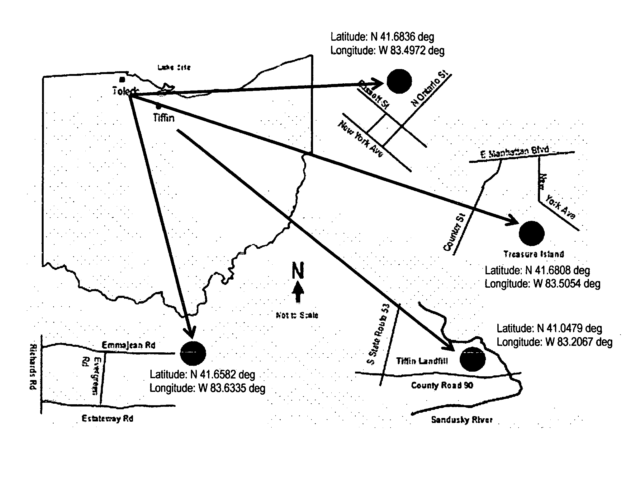
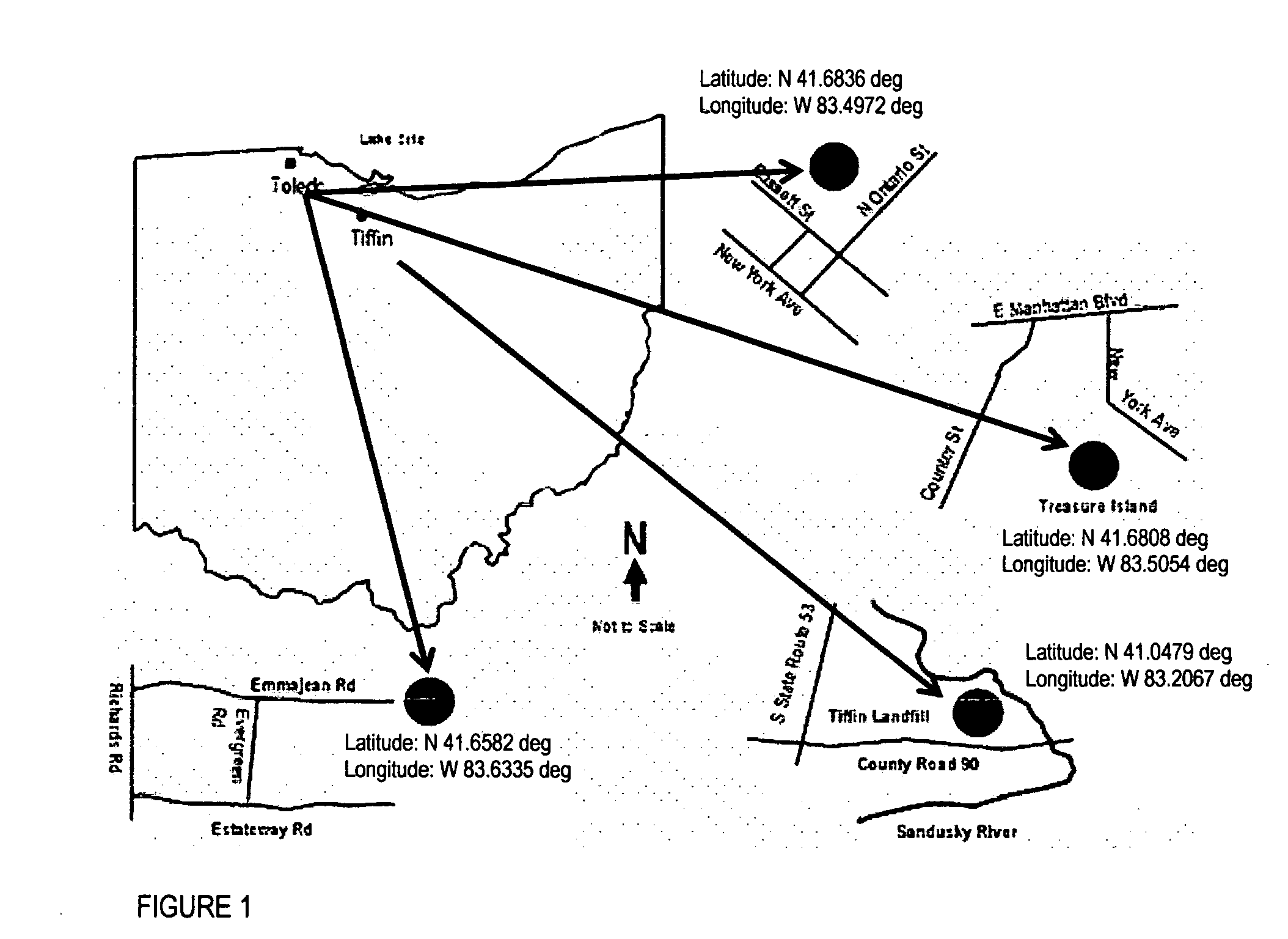
[0049]Treasure Island Dump, a municipal and industrial waste dump, has a footprint of 5.3 hectares and lies adjacent to the 9.3 hectare Manhattan Dump (FIG. 1). Treasure Island stopped receiving waste in 1968 (Mannik & Smith, 2006) and is currently listed as a Super Fund Site (USEPA, 2000).

[0050]In 1981, Owens-Illinois, Inc. and Libbey Plant 27, a glass manufacturing plant, submitted a CERCLA Notification of Hazardous Waste Site (103[c]) form listing unknown quantities of arsenic and heavy metals at the site. In 1993, a screening site inspection was conducted by PRC Environmental Management, Inc. Groundwater, surface water and sediment samples were tested to determine the presence and concentrations of contaminants. Semi-volatile organic compounds, pesticides and heavy metals were confirmed at the site (Mannik & Smith, 2006).

[0051]The City of Toledo acquired Treasure Island in the mid 1990's and had placed a 6 to 12...


PUM


Abstract

Phytoremediation is an economical method to remove contaminants from soils. Understanding the mechanisms that control adsorption of a contaminant to a soil particle is the first step in designing a phytoremediation project in order to optimize removal of said contaminant. To characterize soil conditions, the following data were collected: a) historical land use information, b) evaluating on-site soils and plants for contaminant identity and concentrations, c) particle size analysis of soil samples, d) estimate total organic matter of soil samples, e) conducting batch adsorption experiments to determine Kd values, varying pH levels and concentrations of standard solutions, g) testing on-site pH of soils, h) testing pH levels of standard solutions prior to and after contact with soils used for batch adsorption experiments, i) conducting alkalinity/hardness tests. Once the conditions are known, experiments can be designed manipulating conditions to find optimal conditions to maximize the removal of a contaminant.

Description

BACKGROUND OF THE INVENTION[0001]The field of this invention is the area of environmental engineering of application in the removal of contaminants in soils, comprising of a method of comprehensive data collection and evaluation to understand the mechanisms that control adsorption and plant growth, which will then enable the manipulation of soil conditions in order to optimize soil conditions to increase the plant uptake of contaminants. The data gained is from a series of soil and plant analyses comprising: a) historical land use information, b) evaluating soils for target contaminant and concentrations, c) evaluating on-site plants for target contaminant and concentrations, d) particle size analysis of soil samples, e) total organic matter of soil samples, f) conducting batch adsorption experiments to determine Kd values at varying pH levels and varying concentrations of standard solutions, g) conducting on-site pH testing of soils, h) testing pH levels of standard solutions prior...

Claims


Application Information

Patent Timeline
Patent Type & Authority Applications(United States)
IPC IPC(8): G06F19/00G06F17/10
CPCC02F3/327B09C1/105
Inventor BUCHANAN, CATHERINE LYNN
Owner BUCHANAN CATHERINE LYNN
Why Eureka
Try Eureka