Anode and a method of manufacturing an anode

Inactive Publication Date: 2011-06-30
ENFUCELL
View PDF5 Cites 2 Cited by
  • Summary
  • Abstract
  • Description
  • Claims
  • Application Information

AI Technical Summary

Benefits of technology

[0033]In prior art batteries an anode collector was needed to function as a (−) terminal. At that time a separate anode collector was used together with a wet anode paste because otherwise 1) the wet anode paste would flow out from the battery through the (−) terminal hole in the sealing material and because 2) a change in the ambient humidity level would affect the wet anode paste and alter its characteristics by making the performance worse. Both these problems are avoided with the anode material of the invention which eliminates the use of an anode collector.
[0034]When the anode collect

Problems solved by technology

The paste is quite viscous so that the electrolyte is not capable of flowing out.
The problem with this solution is, however, that the connection of the zinc strip to the collector is problematic and that the zinc self discharge is high because of lacking coverage.
Furthermore because of the low conductivity of the anode, an extra collector at the anode is needed.
However, also here, the hydrophilic zinc anode causes high zinc self discharge and unstable conductivity during the discharging process.
Another problem in traditional manufacturing methods to overcome is that the paper shee

Method used


Image

  • Anode and a method of manufacturing an anode
  • Anode and a method of manufacturing an anode
  • Anode and a method of manufacturing an anode

Examples


preparation example

Preparation of an Anode Material of the Invention

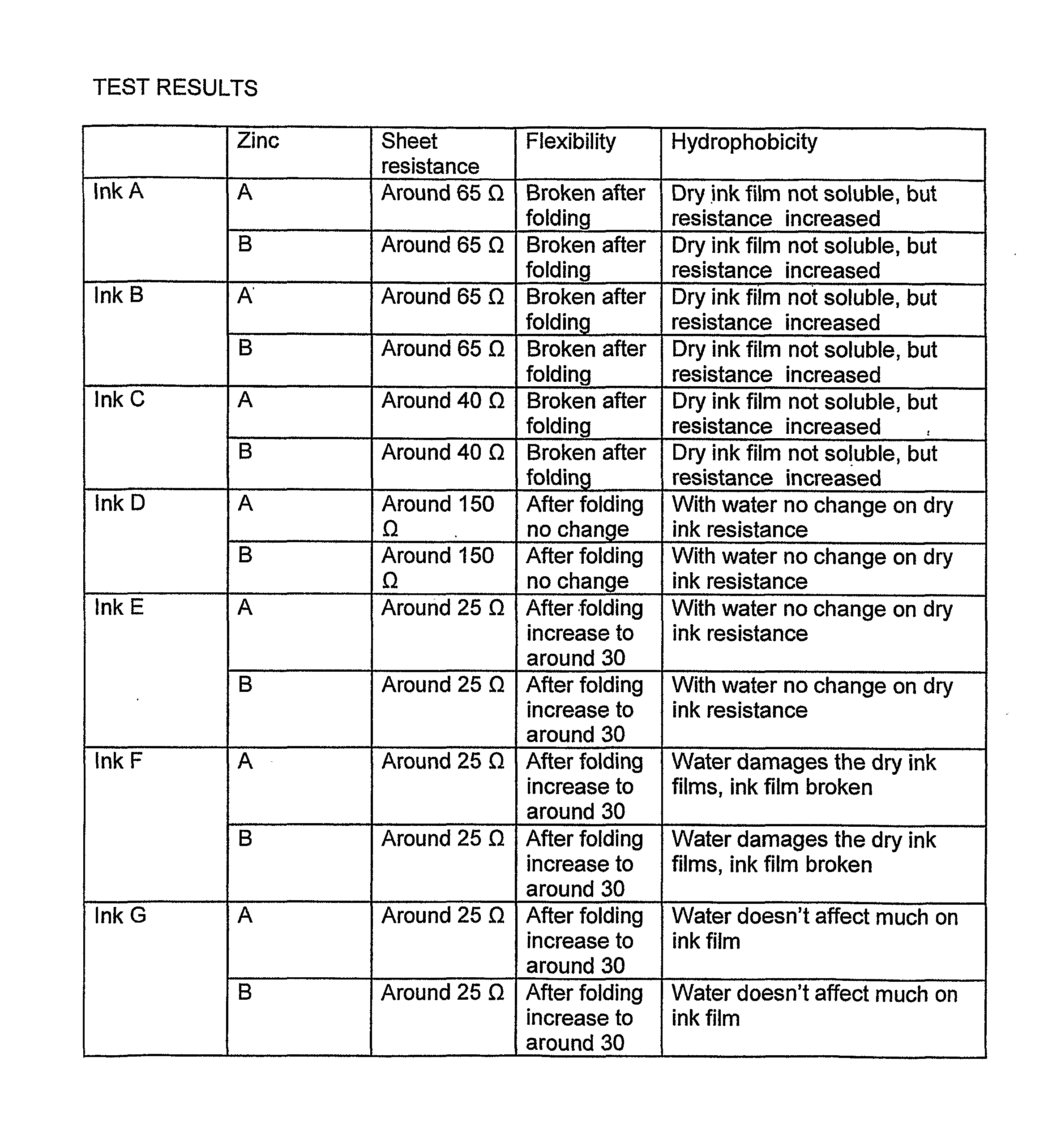
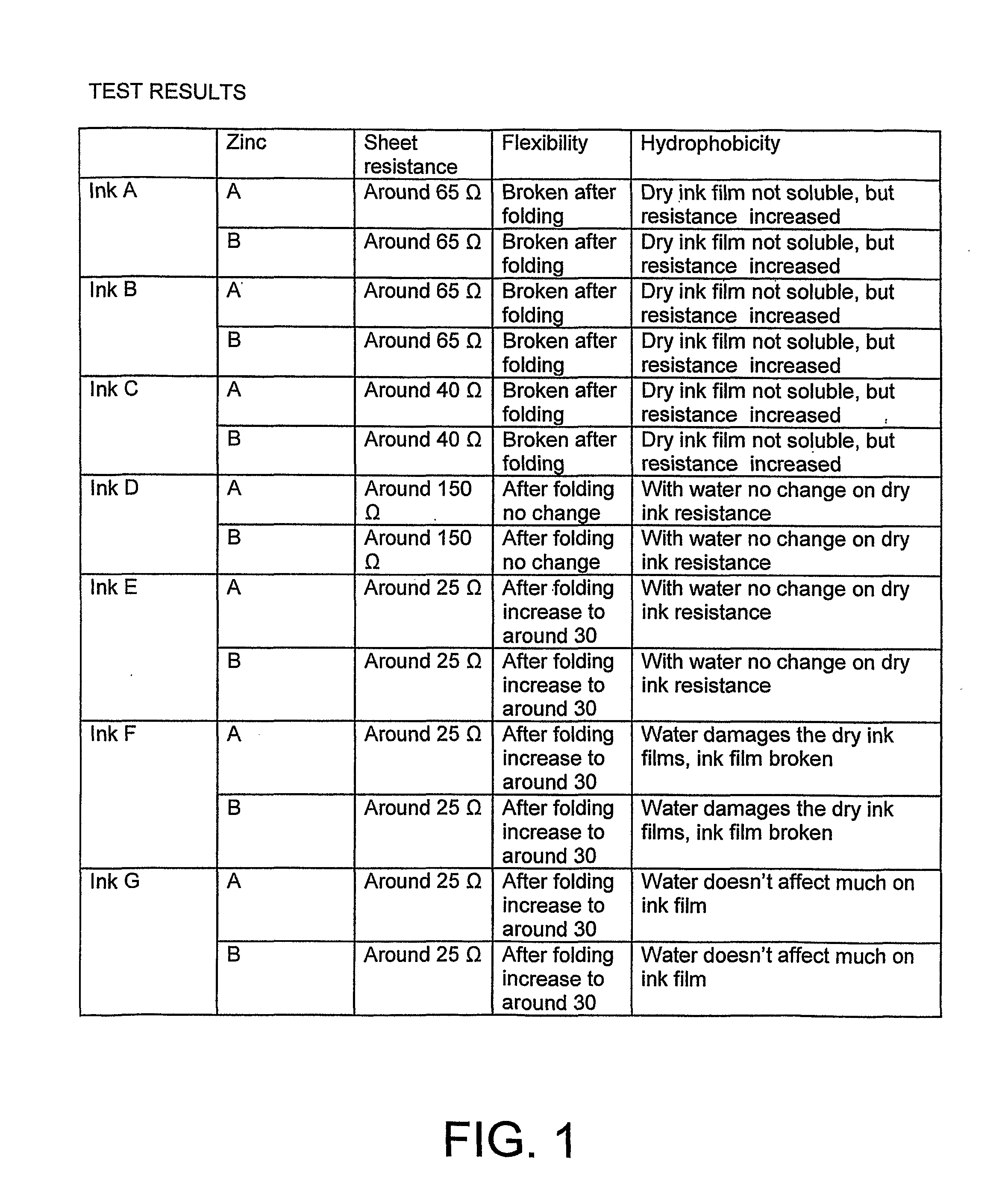
[0047]The anode material (i.e. anode ink) of the invention is prepared by adding zinc powder to conductive carbon ink and keeping stirring until homogeneous as mentioned early. The ink and zinc powder used in the test are Acheson EB 412 and EC-100.

[0048]The conductive carbon ink is stirred with a speed of e.g. 300 rpm and the zinc powder is added gradually. When the zinc powder has been added, the speed of the mixer is gradually increased up to 2000 rpm and the blend is further stirred in about 30 minutes.

[0049]The mixing in the way it is done in the invention gives a good result of anode performance, since peeling problems, conductivity problems an uneven conductivity is avoided. A proper viscosity of the anode material is needed. If the viscosity is too low, then zinc particles will deposit to the bottom. A suitable viscosity of the ink is: Brookfield 20° C. 20 RPM 20000 mPaS to 28000 mPa·S. The mixing quality can be controlled by t...


PUM

PropertyMeasurementUnit
Temperatureaaaaaaaaaa
Thicknessaaaaaaaaaa

Abstract

The printed battery has cathode and anode electrodes with terminals to connect to an external circuit, separator therebetween and electrolyte. An anode electrode material is applied on one side of the separator and a cathode electrode material on the opposite side. The anode material is dry and hydrophobic and is prepared by providing an anode active material, conductive material, solvent and a binder that are mixed to form an anode ink. The anode ink is applied on a substrate and then dried. In response to the drying, the solvent evaporates and the anode ink forms a film on the substrate. The prepared anode material is applied on the separator. An electrolyte solution is printed on the separator that has the anode material thereon. A cathode material is applied between a collector material and separator.

Description

TECHNICAL FIELD[0001]The invention is concerned with an anode for a thin battery and a method for preparing such an anode.BACKGROUND[0002]The basic components of a battery are the electrodes with terminals (electric connections) to connect to an external circuit, a separator to keep the electrodes apart and prevent them from shorting, the electrolyte which carries the charged ions resulting from the chemical reactions taking place at the electrodes and a cover to contain the active chemicals and hold the electrodes in place.[0003]“Wet” cells refer to galvanic cells where the electrolyte is in liquid form and is allowed to flow freely within the cell casing. “Dry” cells are cells that use a solid or powdery electrolyte. Cells with liquid electrolyte can be classified as “dry” if the electrolyte is immobilized by some mechanism, such as by gelling it or by holding it in place with an absorbent substance such as paper.[0004]The most common type of battery used today is the “dry cell” b...

Claims


Application Information

Patent Timeline
IPC IPC(8): H01M6/40H01M4/04
CPCH01M2/1626H01M4/0402H01M4/0407Y10T29/49108H01M4/38H01M6/40Y10T29/49115H01M4/08H01M4/42H01M50/4295H01M50/44H01M4/02
Inventor ZHANG, XIACHANGSHOUJUN, LI
Owner ENFUCELL
Why Eureka
Try Eureka