Liquid-ejecting head, liquid-ejecting apparatus, piezoelectric element, and method for manufacturing liquid-ejecting head

Inactive Publication Date: 2011-07-07
SEIKO EPSON CORP
View PDF14 Cites 18 Cited by
  • Summary
  • Abstract
  • Description
  • Claims
  • Application Information

AI Technical Summary

Benefits of technology

[0019]In accordance with still another aspect of the invention, a method for manufacturing a liquid-ejecting head according to the aspect described above includes forming a STO precursor film on the platinum layer, the STO precursor film being a precursor of the STO layer, forming a piezoelectric precursor film on the STO precursor film, the piezoelectric precursor film being a precursor of the piezoelectric layer, and simultaneously firing the STO precursor film and the piezoelectric precursor film to form the STO layer and the piezoelectric layer. A laminate of the STO layer and the piezoelectric layer can be relatively

Problems solved by technology

However, BiFeO3-based piezoelectric materials have low insulating capacity and sometimes generate leakage current.
These problems are not confined t

Method used


Image

  • Liquid-ejecting head, liquid-ejecting apparatus, piezoelectric element, and method for manufacturing liquid-ejecting head
  • Liquid-ejecting head, liquid-ejecting apparatus, piezoelectric element, and method for manufacturing liquid-ejecting head
  • Liquid-ejecting head, liquid-ejecting apparatus, piezoelectric element, and method for manufacturing liquid-ejecting head

Examples


first embodiment

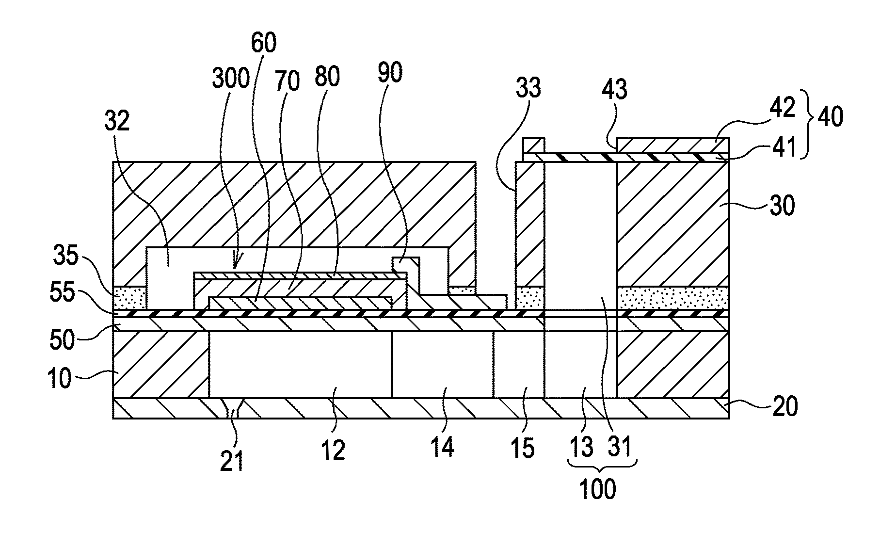
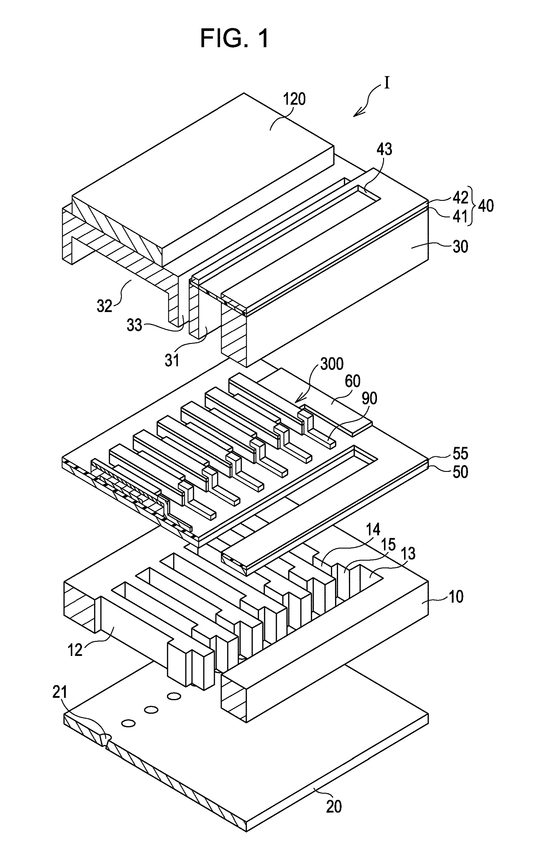
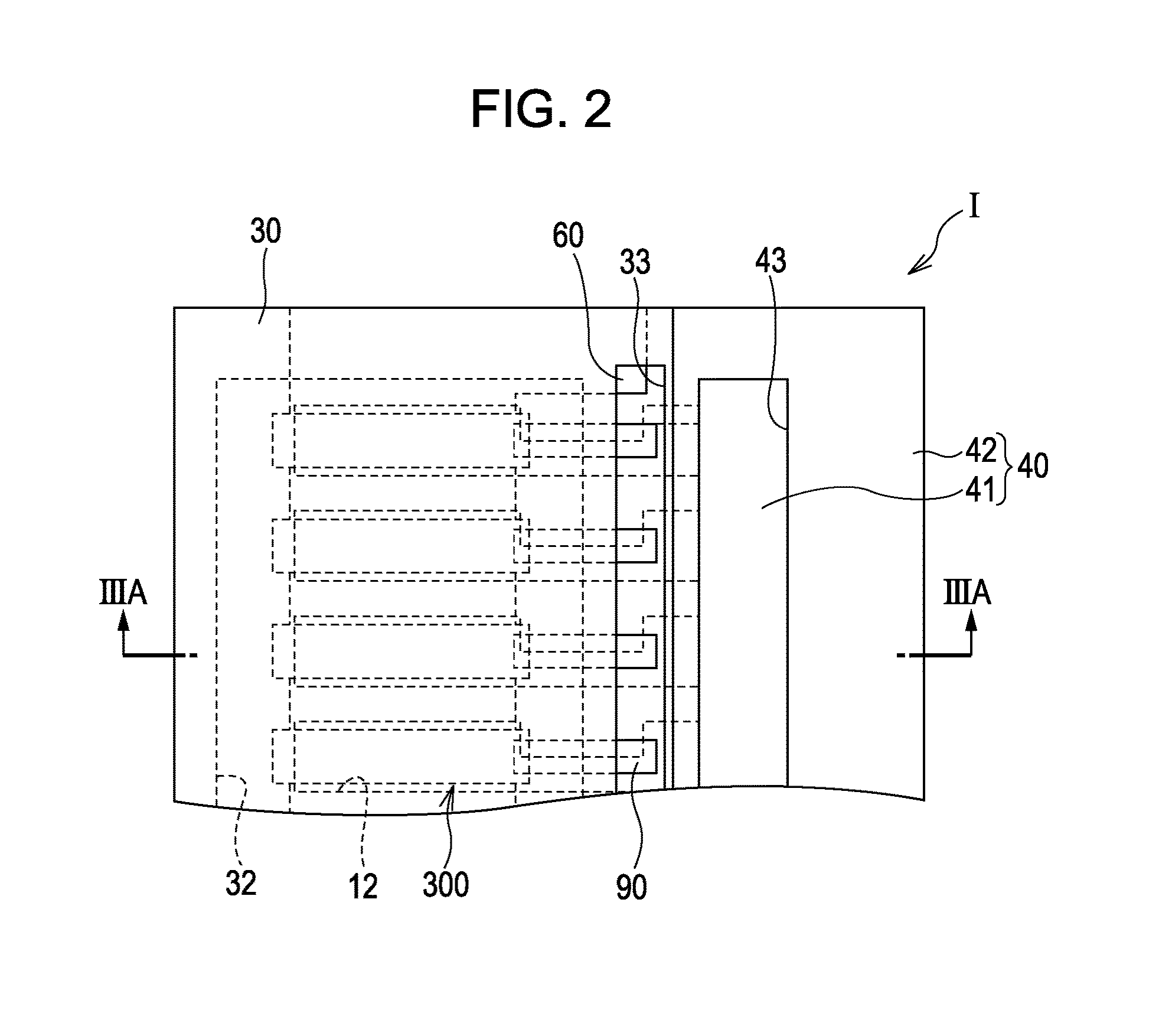
[0070]FIG. 1 is a schematic exploded perspective view of an ink jet print head as an example of a liquid-ejecting head manufactured by a method according to a first embodiment of the invention. FIG. 2 is a fragmentary plan view of the print head according to the first embodiment. FIG. 3A is a cross-sectional view of the print head taken along the line IIIA-IIIA in FIG. 2. FIG. 3B is an enlarged cross-sectional view of a principal part of the print head according to the first embodiment.

[0071]As illustrated in FIGS. 1 and 3, a flow-passage-forming substrate 10 according to the present embodiment is a silicon single crystal substrate. A silicon dioxide elastic film 50 is disposed on the flow-passage-forming substrate 10.

[0072]The flow-passage-forming substrate 10 includes a plurality of pressure-generating chambers 12 juxtaposed to each other in the width direction. The flow-passage-forming substrate 10 further includes a communication portion 13 outside the pressure-generating chambe...

second embodiment

[0118]In the first embodiment, the first electrode 60 includes the STO layer or the SRO layer as the orientation control layer on the platinum layer 62 so that the piezoelectric layer containing bismuth lanthanum iron-manganese oxide contains crystals preferentially oriented in the (111) plane. In the present embodiment, the first electrode 60 includes a platinum layer containing platinum disposed on an iridium oxide layer containing iridium oxide. The components of an ink jet print head according to the present embodiment other than the first electrode 60 are the same as in the first embodiment and will not be further described.

[0119]In the present embodiment, the first electrode 60 includes an iridium oxide layer containing iridium oxide having a thickness in the range of 30 to 80 nm and a platinum layer containing platinum having a thickness in the range of 50 to 200 nm, layered in this order on the elastic film 50. The piezoelectric layer 70 is disposed on the platinum layer.

[01...

example 1

[0127]A surface of a silicon substrate was thermally oxidized to form a silicon dioxide film. A zirconium oxide film having a thickness of 400 nm was then formed on the silicon dioxide film by RF sputtering. A titanium film having a thickness of 20 nm was then formed on the zirconium oxide film by DC sputtering. A platinum film having a thickness of 130 nm was then formed on the titanium film by DC sputtering. A Nb-STO sol-gel solution was then applied to the platinum film by spin coating at 500 rpm and subsequently 3000 rpm for 30 seconds, was dried at 300° C. for three minutes, and was degreased to form a STO precursor film.

[0128]A piezoelectric layer was then formed on the STO precursor film by spin coating in the following manner. First, solutions of bismuth 2-ethylhexanoate, lanthanum 2-ethylhexanoate, iron 2-ethylhexanoate, or manganese 2-ethylhexanoate in xylene and octane were mixed at a predetermined ratio to prepare a precursor solution. The precursor solution was dropped ...


PUM

PropertyMeasurementUnit
Angleaaaaaaaaaa
Volumeaaaaaaaaaa
Widthaaaaaaaaaa

Abstract

A piezoelectric element comprising a first electrode, a piezoelectric layer containing bismuth lanthanum iron and manganese formed above the first electrode, and a second electrode formed above the piezoelectric layer. The piezoelectric layer contains crystals preferentially oriented in a (111) plane.

Description

CROSS-REFERENCE TO RELATED APPLICATIONS[0001]This application claims the benefit of priority to Japanese Patent Application No. 2010-000830 filed Jan. 5, 2010, and Japanese Patent Application No. 2010-154317 filed Jul. 6, 2010,the contents of which are hereby incorporated by reference in their entirety.BACKGROUND[0002]1. Technical Field[0003]The present invention relates to a piezoelectric element, a liquid-ejecting head including the piezoelectric element, a liquid-ejecting apparatus including the piezoelectric element, and a method for manufacturing the liquid-ejecting head. The piezoelectric element includes a piezoelectric layer and electrodes through which a voltage is applied to the piezoelectric layer. The piezoelectric element produces a pressure change in a pressure-generating chamber in communication with a nozzle opening.[0004]2. Related Art[0005]One example of piezoelectric elements for use in liquid-ejecting heads includes a piezoelectric layer between two electrodes. T...

Claims


Application Information

Patent Timeline
IPC IPC(8): B41J2/045H01L41/16H01L41/22B41J2/055B41J2/135B41J2/14B41J2/16H01L41/047H01L41/09H01L41/18H01L41/187H01L41/317H01L41/319H01L41/43
CPCB41J2/055Y10T29/42B41J2/161B41J2/1628B41J2/1629B41J2/1634B41J2/1642B41J2/1645B41J2/1646B41J2002/14241B41J2002/14419B41J2202/03H01L41/187H01L41/316H01L41/318H01L41/319H01L41/0973B41J2/14233H10N30/2047H10N30/853H10N30/079H10N30/076H10N30/078
Inventor KOBAYASHI, TOMOKAZUNAWANO, MASAHISA
Owner SEIKO EPSON CORP
Why Eureka
Try Eureka