

Component made of a stack of ceramic plates
a technology of ceramic plates and components, applied in the direction of instruments, physical/chemical process catalysts, gas-gas reaction processes, etc., can solve the problems of inability to clean, inability to maintain and inspect, and permanent connection of parts, etc., to achieve considerable facilitation of handling, improve endurance, and improve mechanical stability
- Summary
- Abstract
- Description
- Claims
- Application Information
AI Technical Summary
Benefits of technology
Problems solved by technology
Method used
Image

Examples
example 1
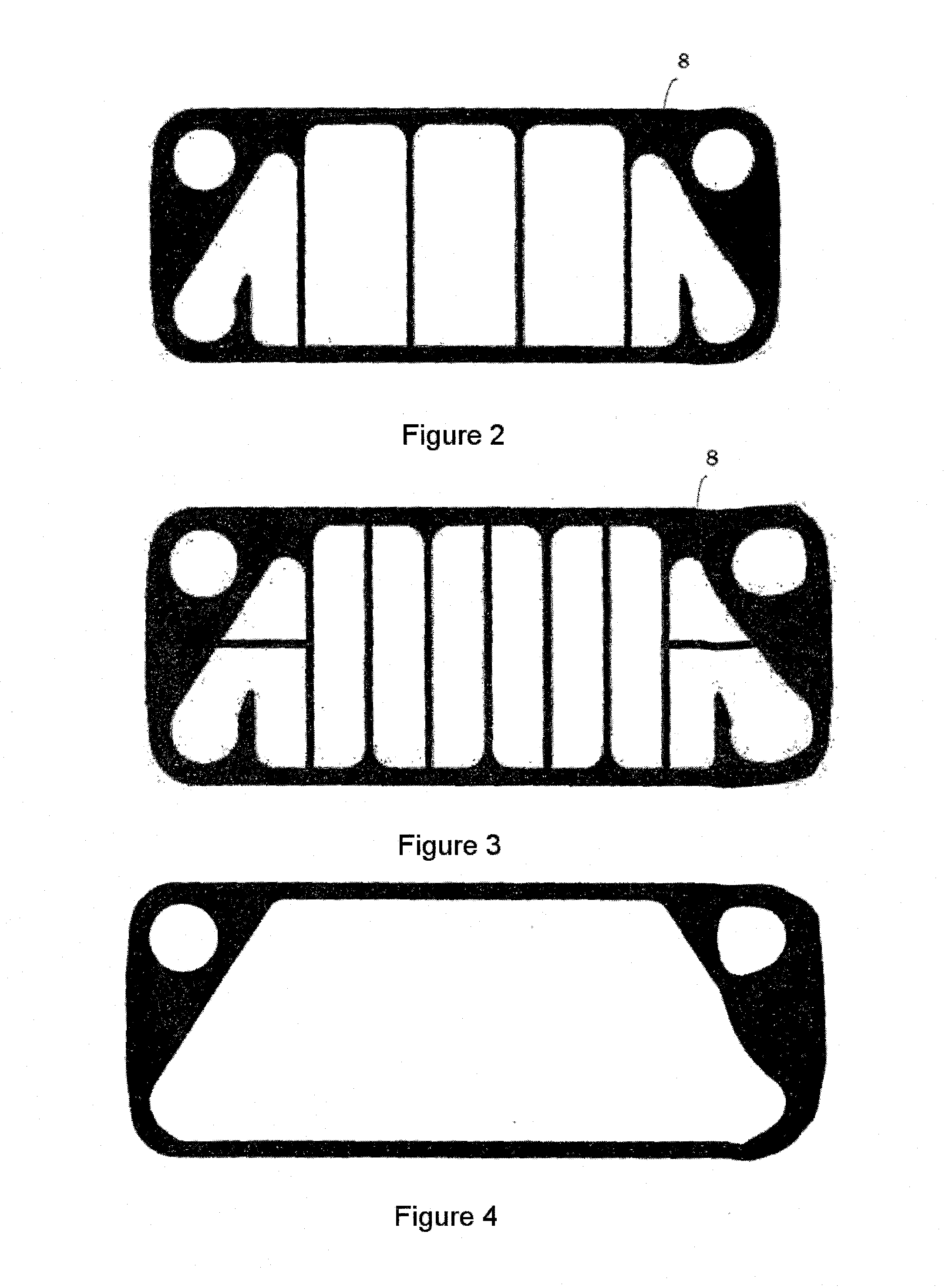
Heat Exchanger Comprising PTFE, Design FIG. 2, Web Surface 50%, Thickness 0.5 mm
[0076](1) SSiC plates with a bimodal structure are used, 50 to 90 vol % of the grain size distribution consisting of prismatic SiC crystallites in platelet form with a length of from 100 to 1500 μm, and 10 to 50 vol % of prismatic SiC crystallites in platelet form with a length of from 5 to less than 100 μm (EKasic® C from ESK Ceramics GmbH & Co.). The SSiC plates have a length of 500 mm, a width of 200 mm and a thickness of 6.5 mm.
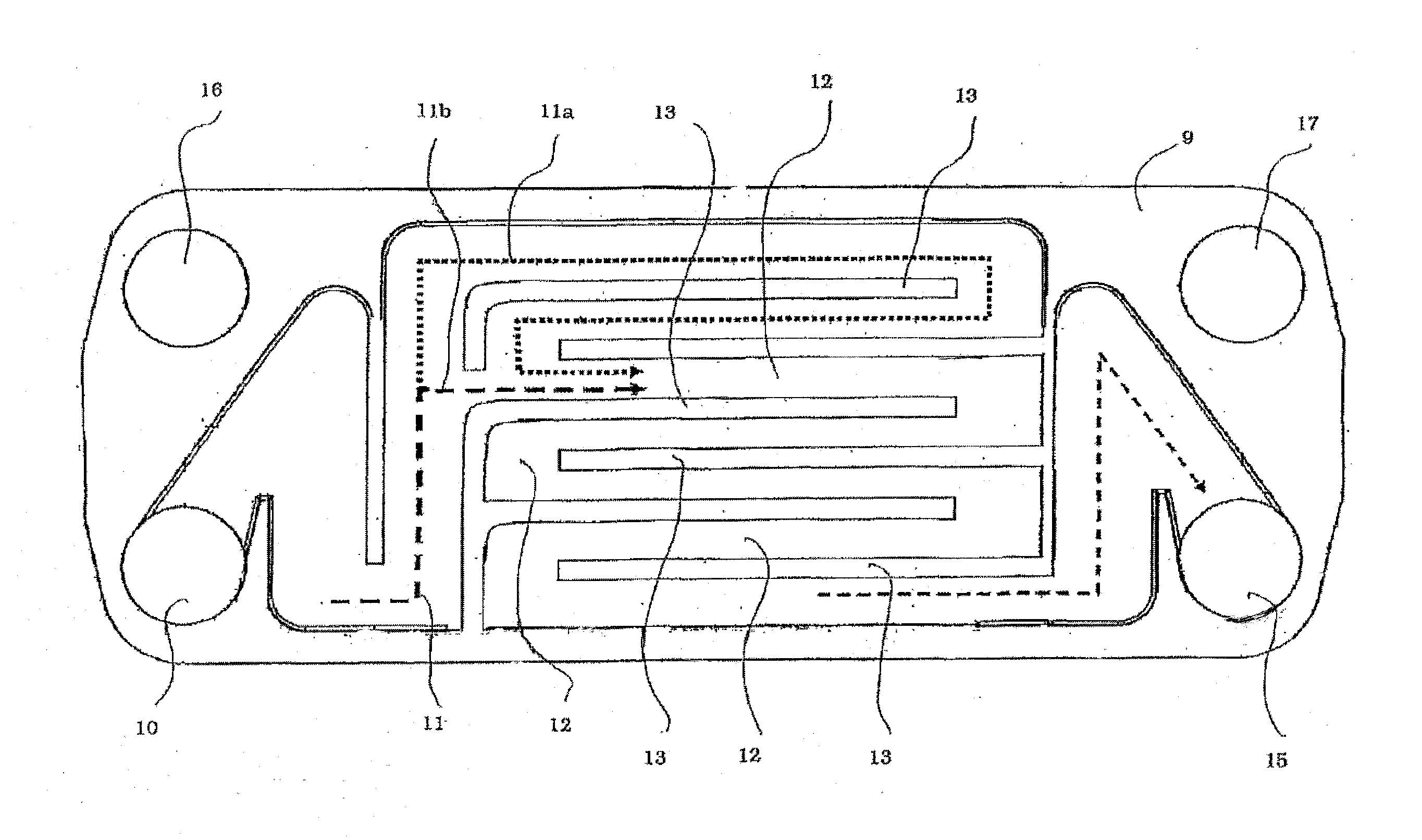
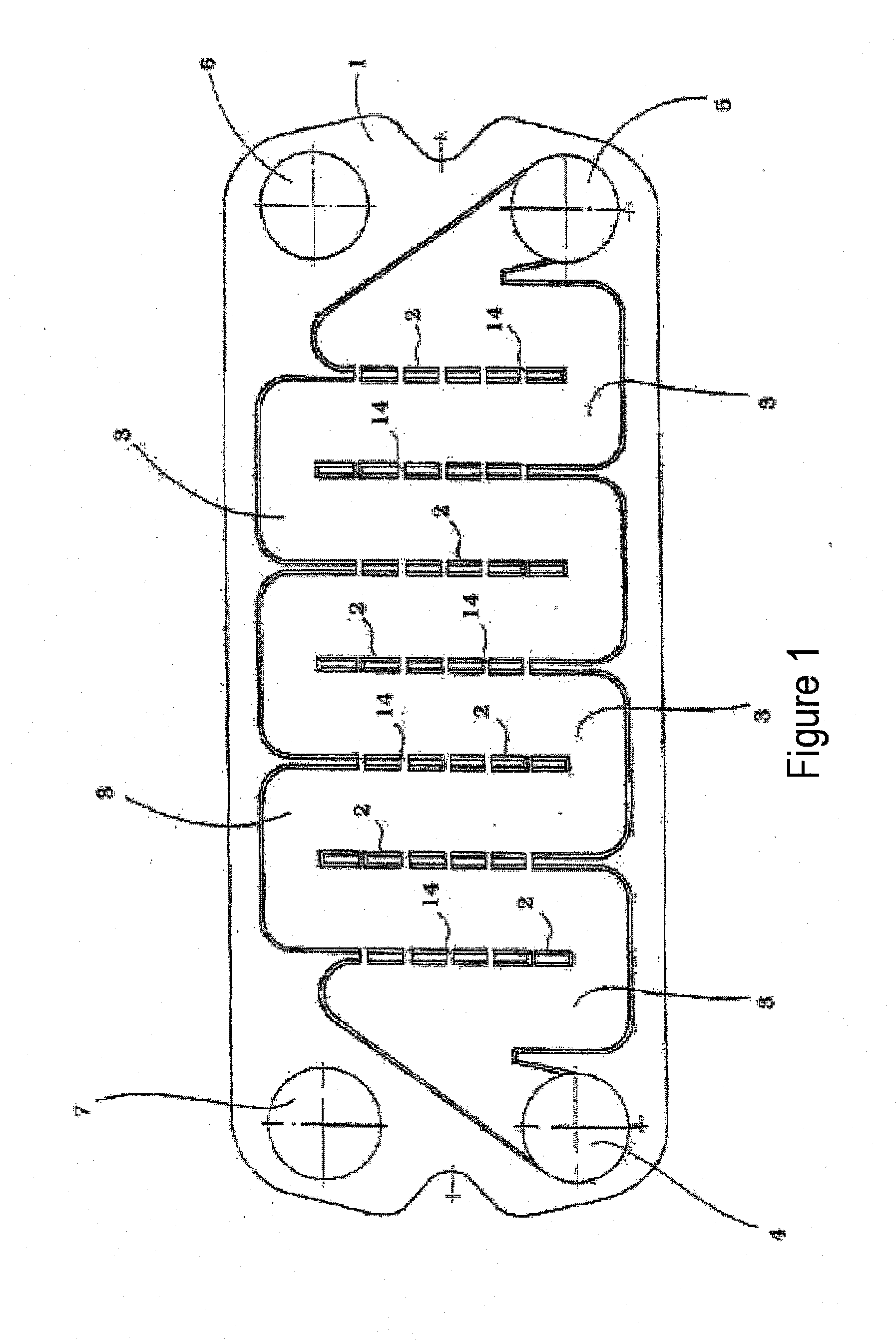
[0077](2) In order to produce a heat exchanger unit, four (intermediate) plates as well as a base plate and a cover plate are used. Incorporated into the intermediate plates, there are 3.5 mm deep guide channels according to the type of FIG. 1, which form the subsequent channel system. The base plate and the cover plate do not contain a channel structure, and the cover is provided with inlet openings. The plates are arranged in the unit so that two material flows can exchange ...
example 2
Heat Exchanger Comprising PTFE, Design FIG. 3, Web Surface 100%, Thickness 0.7 mm
[0085](1) SSiC plates made of EKasic® C (structure and distortion as described in Example 1) with a length of 500 mm, a width of 200 mm and a thickness of 6.5 mm are used.
[0086](2) The heat exchanger unit consists of four (intermediate) plates as well as a base plate and a cover plate, which are connected in countercurrent flow.
[0087](3-5) A 0.7 mm thick ePTFE sheet with the designation WT-A (maximum deformation up to about 50% of its initial thickness) is used as the seal. The design of the seal corresponds to FIG. 3. It is characterized in that besides the circumferential sealing surface in the outer region of the SSiC plates used, 100% of the upper sides of the ceramic webs are also covered with sealing material. The cutting is carried out by water-jet cutting.
[0088](6) The plates and sheets are cleaned with compressed air and are clamped in the metal frame between two steel plates.
[0089](7) For the ...
example 3
Heat Exchanger Comprising PTFE, Design FIG. 2, Web Surface 50%, Thickness 0.5 mm, Plates with Grooves
[0090](1) SSiC plates made of EKasic® C (structure and distortion as described in Example 1) with a length of 500 mm, a width of 200 mm and a thickness of 6.5 mm are used.
[0091](2) In order to produce a heat exchanger unit, four (intermediate) plates as well as a base plate and a cover plate are used. Incorporated into the intermediate plates, there are 3.5 mm deep guide channels which form the subsequent channel system, as well as a rectangular circumferential groove with a depth of 2 mm±0.1 mm. The base plate and the cover plate do not contain a channel structure, and the cover is provided with inlet openings. The plates are arranged in the unit so that two material flows can exchange heat in countercurrent flow.
[0092](3-5) The 0.5 mm thick ePTFE sheet with the designation WT-A, as described in Example 1, is used as the sealing material. The design of the flat seal corresponds to F...
PUM
| Property | Measurement | Unit |
|---|---|---|
| thickness | aaaaa | aaaaa |
| thickness | aaaaa | aaaaa |
| thickness | aaaaa | aaaaa |
Abstract
Description
Claims
Application Information