Mass spectrometer
a mass spectrometer and mass spectrum technology, applied in the field of mass spectrometers, can solve the problems of severe deterioration of the s/n of the mass spectrum, easy irradiation of excitation light onto one same ion for a comparatively long time, etc., and achieve the effects of enhancing the s/n of the ms/ms spectrum, preventing secondary dissociation, and enhancing the primary dissociation of a precursor
- Summary
- Abstract
- Description
- Claims
- Application Information
AI Technical Summary
Benefits of technology
Problems solved by technology
Method used
Image
Examples
first embodiment
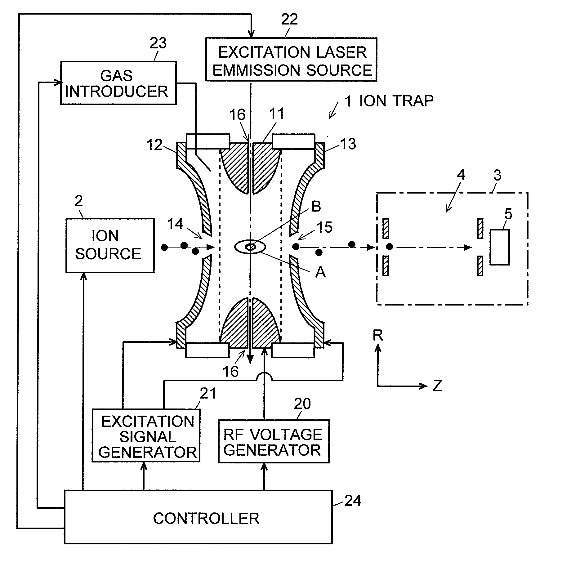
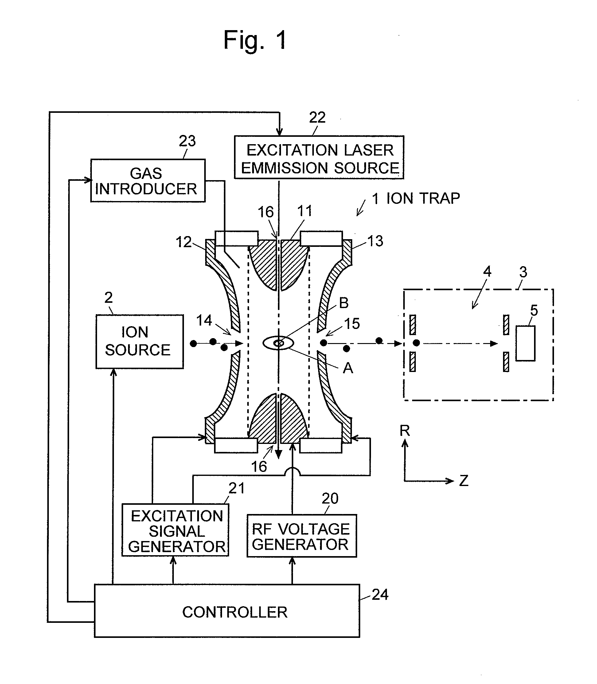
[0054]FIG. 1 is a schematic configuration diagram of an ion trap time-of-flight mass spectrometer (IT-TOFMS) according to an embodiment (the first embodiment) of the first aspect of the present invention.
[0055]Inside an evacuated vacuum chamber (not shown), a three-dimensional quadrupole type ion trap 1 is disposed. The ion trap 1 is composed of a ring electrode 11 and a pair of end cap electrodes 12, 13 opposing each other (right and left in FIG. 1) with the ring electrode therebetween. The inner surface of the ring electrode is formed hyperboloid-of-one-sheet-of-revolution and the inner surface of the end cap electrodes are formed hyperboloid-of-two-sheets-of-revolution. These electrodes 11, 12, and 13 form a trapping space A for trapping ions by a trapping electric field in the space surrounded thereby.
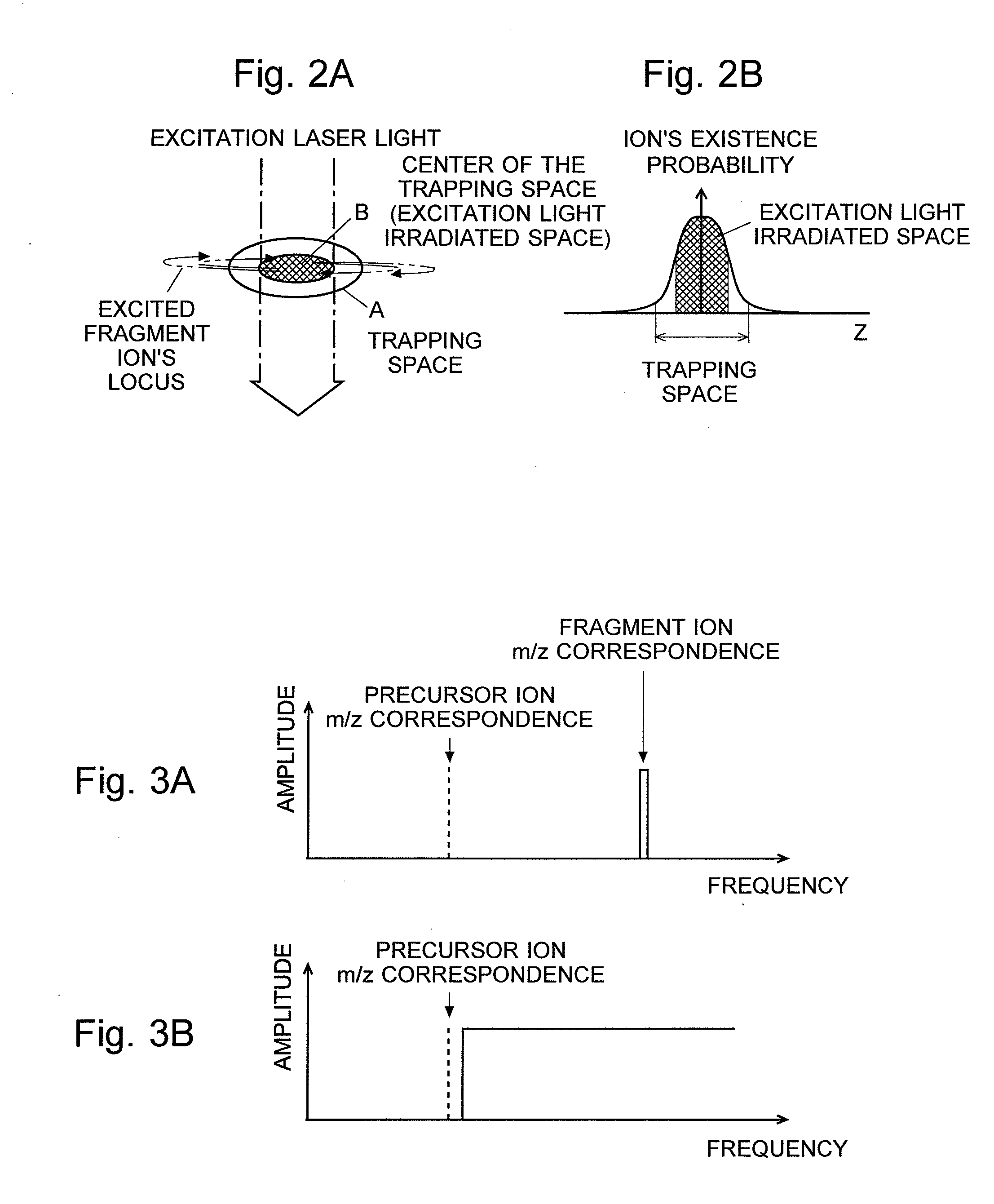
[0056]Outside an entrance aperture 14 bored through the entrance-side end cap electrode 12, an ion source 2 such as a MALDI for example is placed. On the other hand, outside an exi...
second embodiment
[0077]FIG. 5 is a schematic configuration diagram of an ion trap time-of-flight mass spectrometer (IT-TOFMS) according to an embodiment (the second embodiment) of the second aspect of the present invention. In FIG. 5, like elements are denoted by like numerals as in the first embodiment which was described earlier.
[0078]One of the essential differences between the second embodiment and the first is that the excitation laser light is not irradiated to the center of the trapping space A of the ion trap 1, but is purposely irradiated to the area off the center. For this purpose, the laser irradiation aperture 17 is placed off the center axis of the ring electrode 11. In addition, the excitation signal generator 25 applies an excitation signal having a frequency that selectively makes a precursor ion to be targeted vibrate (but not making a fragment ion vibrate) to the end cap electrodes 12 and 13 when making a photodissociation occur by irradiating a laser light. In this case, the exci...
PUM
 Abstract
Description
Claims
Application Information
 - R&D
- Intellectual Property
- Life Sciences
- Materials
- Tech Scout
- Unparalleled Data Quality
- Higher Quality Content
- 60% Fewer Hallucinations
Browse by: Latest US Patents, China's latest patents, Technical Efficacy Thesaurus, Application Domain, Technology Topic, Popular Technical Reports.
© 2025 PatSnap. All rights reserved.Legal|Privacy policy|Modern Slavery Act Transparency Statement|Sitemap|About US| Contact US: help@patsnap.com


