Functional optical coherent imaging

a functional optical and coherent imaging technology, applied in the field of functional optical coherent imaging, can solve the problems of difficulty in distinguishing sufficiently the signal of interest from all the other information acquired, and achieve the effects of enhanced hemodynamic response, high spatial resolution, and good statistical confiden

Active Publication Date: 2011-07-14
ECOLE POLYTECHNIQUE FEDERALE DE LAUSANNE (EPFL)
View PDF9 Cites 30 Cited by
  • Summary
  • Abstract
  • Description
  • Claims
  • Application Information

AI Technical Summary

Benefits of technology

[0035]An advantage of the invention is that a total instrument platform is described, which overcomes the aforementioned limitations and which allows the extraction with high spatial resolution and good statistical confidence of the so-called fOCI maps as a result of a herein disclosed statistical analysis representing the locally enhanced microcirculation in response to internal or external stimuli.
[0036]According to the invention an overlay of the results of the statistical analysis is possible i.e. the so-called t-values over the conventional digitized image showing the locally enhanced hemodynamic response. This statistical test is by no means the only statistical test procedure—more statistical tests are known by those skilled in the art.
[0037]Further, according to the invention it becomes possible to build a general stimuli unit which allows the emission of stimulus signals (optical, acoustical, electrical, images etc.) and/or pictures or representations of objects (to be named) and to monitor precisel

Problems solved by technology

As set out already in section Background of the invention, several optical methods exist for imaging microcirculation, however they suffer from various limitatio

Method used


Image

  • Functional optical coherent imaging
  • Functional optical coherent imaging
  • Functional optical coherent imaging

Examples


Embodiment Construction

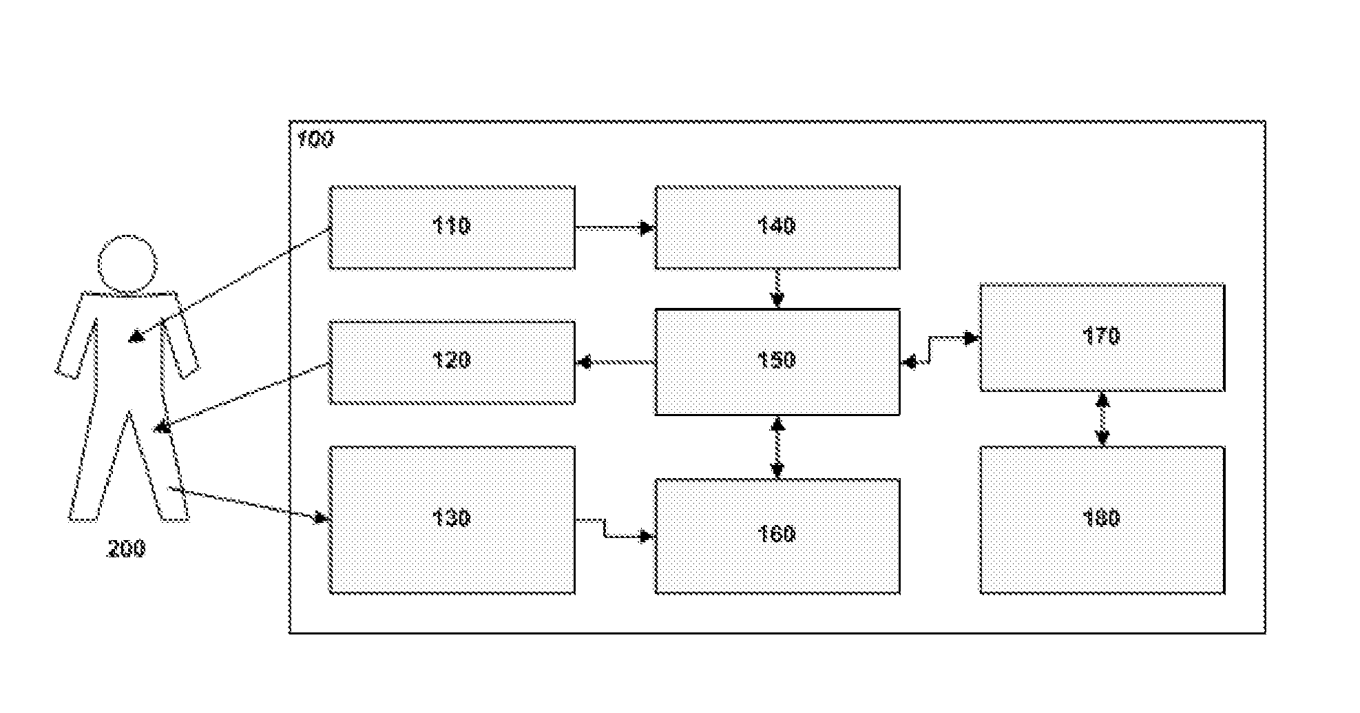
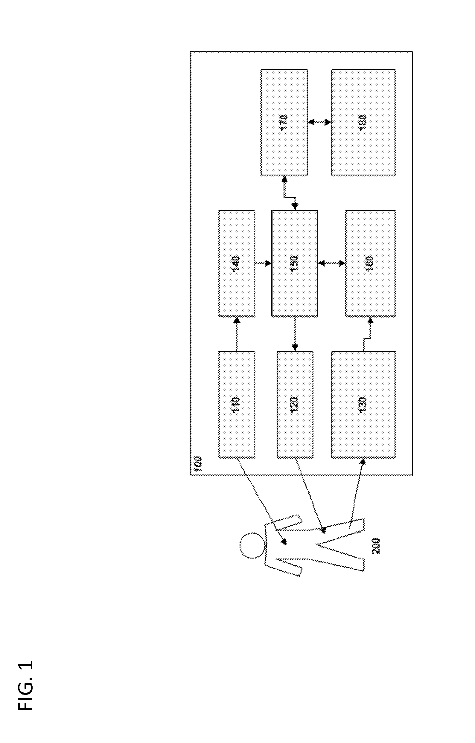
[0055]FIG. 1 is a block diagram of the Functional Optical Coherent Imaging (fOCI) system platform according to a preferred embodiment of the invention for measuring microcirculation in response to stimulation and generating fOCI-maps of a subject 200. Therefore it is provided at least one Active Camera Unit ACU 110 and Image Processing Unit(s) IPU 140, a multi-modal Stimulation Unit(s) STU 120, and the Body Function Reference Measurement Unit(s) BFMU 130 monitoring the time course of preselected body parameters, all linked to a Central Clock and Processing Unit CCU 150, to which a Statistical Analysis Unit SAU 160 is attached for analyzing and monitoring hemodynamic and optical blood property response to the preplanned stimulation. This result is represented as at least one map for diagnosis and can be visualized on the Human Operator Interface HOI 170 which can be connected to a Picture Archiving and Communication System PACS 180.

[0056]Referring to FIG. 1, a general illustration of...


PUM


Abstract

The present invention relates to a functional optical coherent imaging (fOCI) platform comprising at least one active camera unit (ACU) comprising a coherent and/or a partially coherent light source, and means for spectral filtering and imaging a selected body area of interest; an image processing unit (IPU) for pre-processing data received from an ACU; at least one stimulation unit (STU) transmitting a stimulation to a subject; at least one body function reference measurement unit (BFMU); a central clock and processing unit (CCU), with interconnections to the ACU, the IPU, the STU, for collecting pre-processed data from the IPU, stimuli from the STU body function reference data from the BFMU in a synchronized manner; a post-processing unit (statistical analysis unit, SAU); and an operator interface (HOD. Further the invention relates to a process for acquiring stimuli activated subject data comprising the steps of aligning a body function unit at a subject and monitoring pre-selected body function; selecting a stimulus or stimuli; imaging a body area of interest; exerting one or a series of stimuli on the subject; imaging the body area of interest synchronous with said stimuli and the preselected body functions; and transferring said synchronized image, stimuli and body function data to a statistical analysis unit (SAU) and performing calculations to generate results pertaining to body functions.

Description

[0001]The present invention relates to a functional optical coherent imaging (fOCI) platform as well as a process for acquiring stimuli activated subject data.DEFINITIONS[0002]In the description the following terms will be used and for which we want to give some definitions.[0003]“Source” is used to mean any source of electromagnetic radiation, preferably a coherent source with sufficient modal stability and a sufficiently long coherence length.[0004]“Detector” is used herein to mean any device capable of measuring energy in an electromagnetic signal as a function of wavelength. A detector array means a plurality of detectors. In general the preferred detector arrays used in this disclosure have their optimal sensitivity in the wavelength range of the used source. The detectors can either be one-, multi-dimensional or line arrays, depending on the optical setup and the optical scan system. In the predominantly used wavelength range of around 800 nm, CMOS detectors have currently the...

Claims


Application Information

Patent Timeline
IPC IPC(8): H04N5/228
CPCA61B3/102A61B3/1233A61B5/0059A61B5/726A61B5/413A61B5/7203A61B5/0066A61B5/0048A61B5/02028A61B5/7278A61B5/742
Inventor LASSER, THEOVAN DE VILLE, DIMITRIMARTIN-WILLIAMS, ERICALEUTENEGGER, MARCELMAERKI, IWANFRIEDRICH, MICHAELVILLIGER, MARTIN
Owner ECOLE POLYTECHNIQUE FEDERALE DE LAUSANNE (EPFL)
Why Eureka
Try Eureka