
Variable Voltage Converter (VVC) with Integrated Battery Charger

a voltage converter and battery charger technology, applied in the direction of motor/generator/converter stoppers, emergency power supply arrangements, process and machine control, etc., can solve the problems of loss of vvc control, power converter is typically unidirectional boost from battery side to motor side and unidirectional buck, etc., to improve isc and optimize hev performance.

Active Publication Date: 2011-07-14
FORD GLOBAL TECH LLC
View PDF20 Cites 37 Cited by
  • Summary
  • Abstract
  • Description
  • Claims
  • Application Information

AI Technical Summary

Benefits of technology

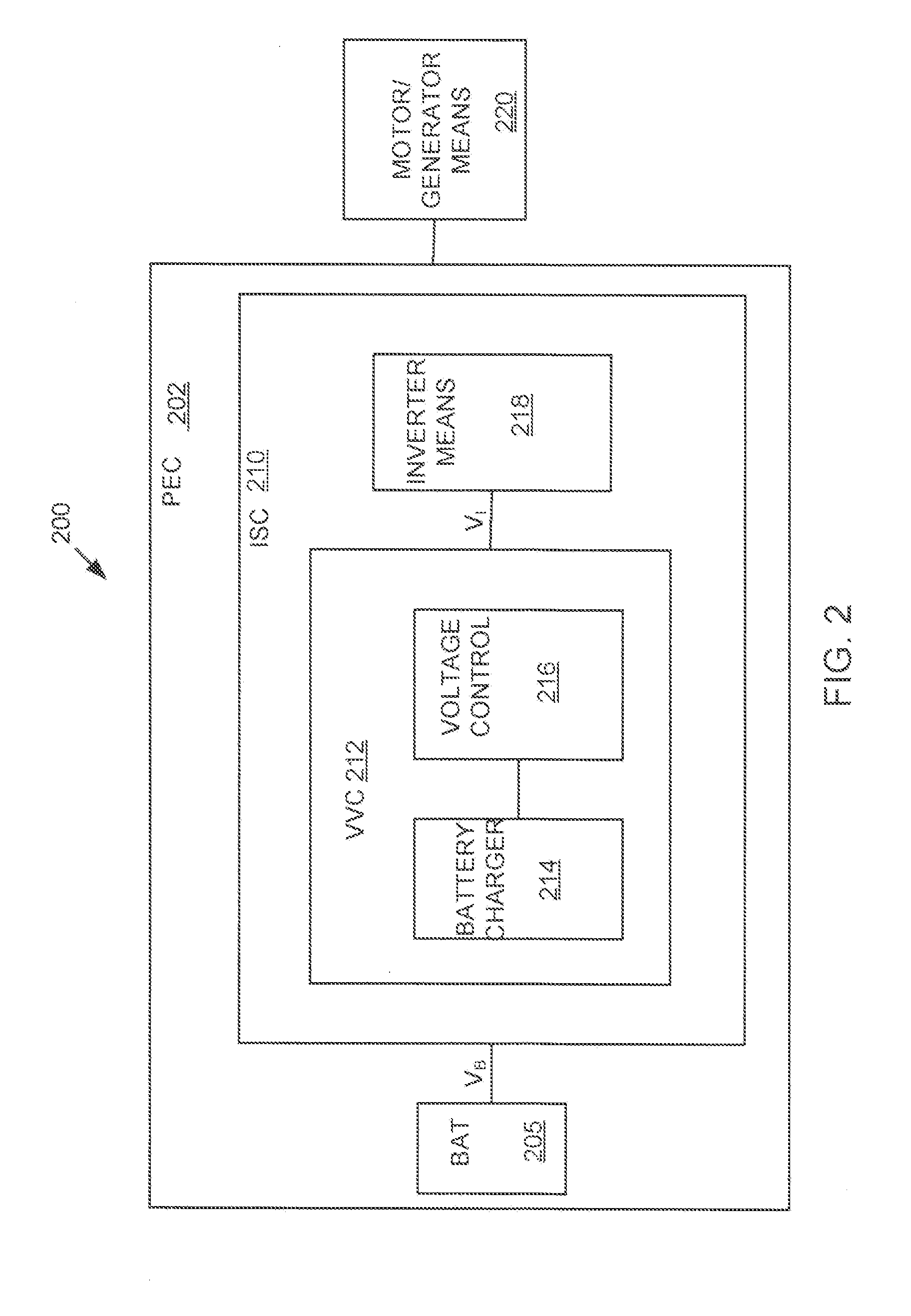
[0010]An example VVC can include a first transistor and a first diode arranged to form the first switching unit, and a second transistor and a second diode arranged to form the second switching unit. The second phase leg of an example VVC can include a third transistor and a third diode arranged to form the third switching unit, and a fourth transistor and a fourth diode arranged to form the fourth switching unit. The various switching units can be individually controlled to obtain a desired VCC output voltage, which can improve and optimize ISC as well as HEV performance. In an exemplary embodiment, a VCC can perform bidirectional voltage reduction as well as bi-directional voltage boost.

Problems solved by technology

While a single power converter can operate as both a boost converter and a buck converter, and therefore support bidirectional power flow, in hybrid vehicle applications, the power converter is typically unidirectional boost from battery side to motor side and unidirectional buck from motor side to battery side.
When the voltage VB becomes higher than VI, a loss of VVC control can result, allowing inrush currents to build up on a VVC inductor within milliseconds, and thereby trigger an undesired system shutdown by over-current protection mechanisms.
Unfortunately, however, maintaining a VI that is greater than VB can distort current output under low speed driving conditions, which in turn can reduce vehicle control and degrade vehicle performance.
The high VI condition can also increase switching power losses and limit inverter capabilities.
However, because the VI of the VVC must be maintained at a higher state than the VB of the VVC, energy cannot be transferred to the battery anytime when the voltage V1 is lower than VB.
However, the PHEV recharging unit is bulky and relatively expensive.
Furthermore, the recharging unit can only be employed while the vehicle is turned off and not in use.

Method used


Image

  • Variable Voltage Converter (VVC) with Integrated Battery Charger
  • Variable Voltage Converter (VVC) with Integrated Battery Charger
  • Variable Voltage Converter (VVC) with Integrated Battery Charger

Examples


Embodiment Construction

[0015]Example embodiments of the invention are presented herein; however, the invention may be embodied in a variety of alternative forms, as will be apparent to those skilled in the art. To facilitate understanding of the invention, and provide a basis for the claims, various figures are included in the specification. The figures are not drawn to scale and related elements may be omitted so as to emphasize the novel features of the invention. Structural and functional details depicted in the figures are provided for the purpose of teaching the practice of the invention to those skilled in the art and are not to be interpreted as limitations. For example, control modules for various systems can be variously arranged and / or combined and may not be depicted in illustrations of example embodiments herein in order to better emphasize novel aspects of the invention.

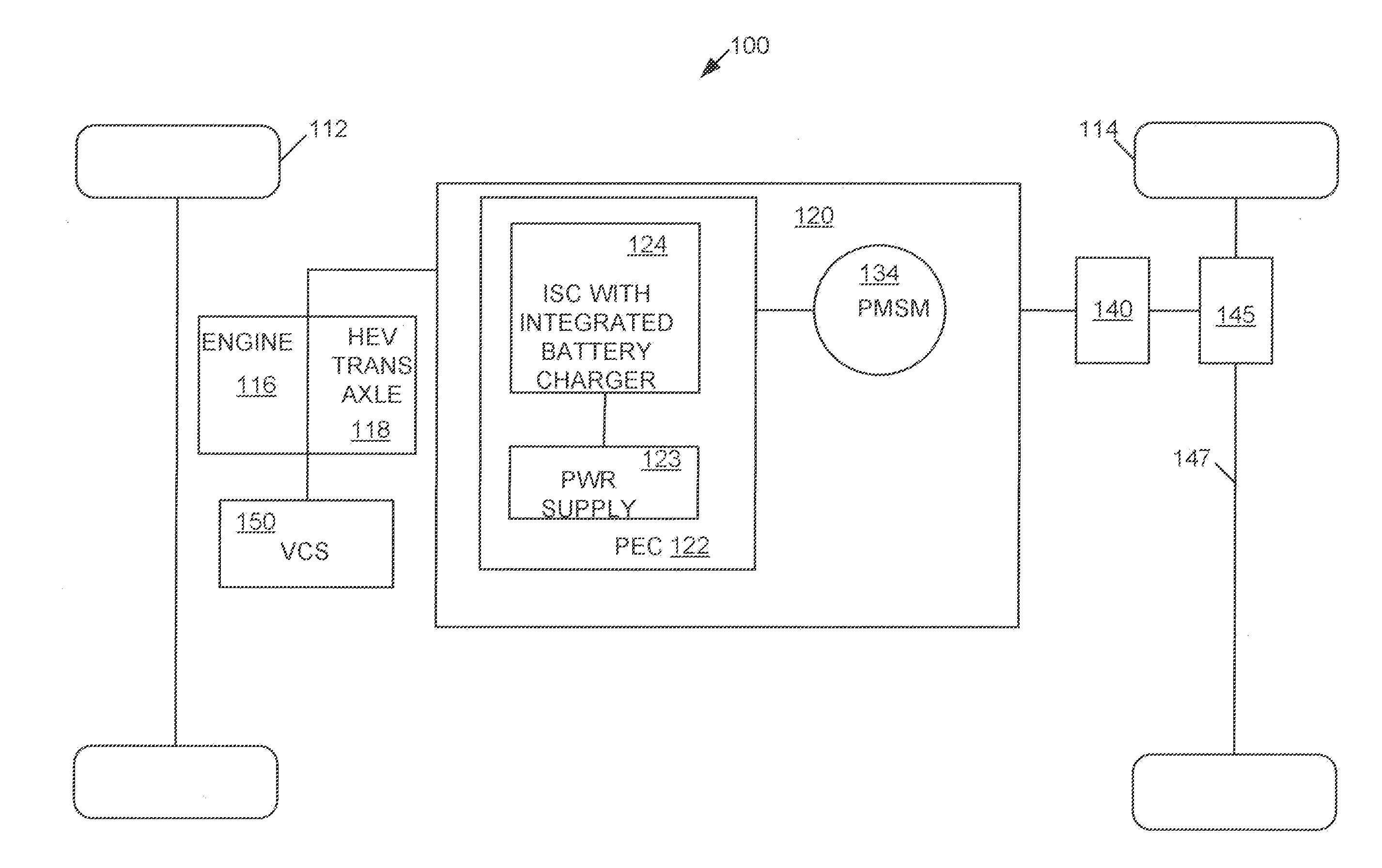
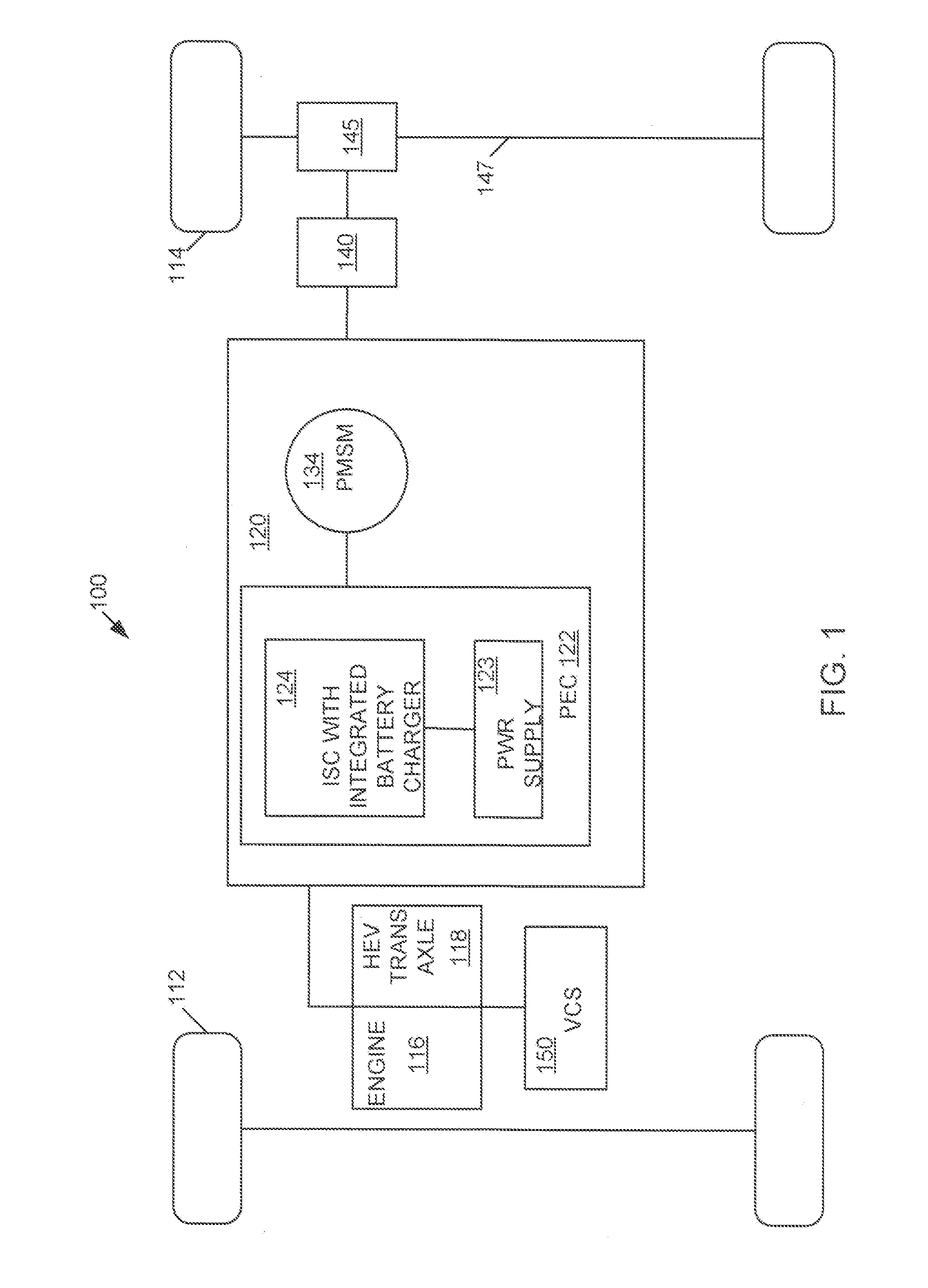
[0016]FIG. 1 illustrates a schematic of an example vehicle 100. The vehicle 100 may be of any suitable type, such as an elec...


PUM


Abstract

A variable voltage converter (VVC) is configured to provide bidirectional voltage boost and buck from an input side to an output side. A VVC can include a voltage control portion and a battery charging portion. When incorporated into an inverter system controller (ISC) for a hybrid electric vehicle, the VVC can be configured to charge a battery during both high and low ISC dc bus voltage conditions. A VVC can be configured to receive power from an ac power source through a plug coupled to the VVC via a soft start rectifier. Accordingly, the VVC with integrated battery charger can be used to charge a battery for a Plug-In Hybrid Electric Vehicle (PHEV) from a standard ac electrical outlet.

Description

FIELD OF INVENTION[0001]The present invention relates generally to power conversion circuits, and more particularly to variable voltage converter in power conversion circuits employed in electric drive systems for hybrid electric vehicles.BACKGROUND OF INVENTION[0002]Hybrid electric vehicles can employ both an electric propulsion system and an internal combustion propulsion system to improve fuel economy and reduce carbon emissions. Electric propulsion can be performed by an electric drive system that can include a number of components, typically at least including a power conversion circuit and a motor. In this arrangement, the power conversion circuit can controllably transfer power from a power source to the motor to drive a load. A high-voltage battery can be used as a power source for the electric drive system. The power conversion circuit provides an interface between the high voltage battery and the electric motor, and can boost a direct current voltage provided by the batter...

Claims


Application Information

Patent Timeline
IPC IPC(8): H02M3/335H02P27/00H02M1/36H02J7/02
CPCB60L11/123B60L11/1814B60L2210/12H02J7/022Y02T10/6217Y02T10/92Y02T10/7077Y02T10/7233Y02T90/127Y02T90/14Y02T10/7005Y02T10/7072B60L50/61B60L53/24H02J7/02H02J2207/20Y02T10/62Y02T10/72Y02T10/70Y02T90/12
Inventor CHEN, LIHUA
Owner FORD GLOBAL TECH LLC
Learn More