Electricity storage device

a technology of electric storage and storage device, which is applied in the direction of non-aqueous electrolyte cells, cell components, electrochemical generators, etc., can solve the problems of difficult to obtain favorable contact interfaces for electrodes manufactured using active materials in powder form, high internal pressure of lithium ion secondary batteries, and low fluidity of solid electrolyte, etc., to achieve small contact resistance at interfaces of electrodes

Active Publication Date: 2011-07-21
SEMICON ENERGY LAB CO LTD
View PDF16 Cites 37 Cited by
  • Summary
  • Abstract
  • Description
  • Claims
  • Application Information

AI Technical Summary

Benefits of technology

[0034]In a structure of a negative electrode of a power storage device including a solid electrolyte, by providing a layer made of a nitride of lithium and a transition metal in contact with the solid electrolyte, adhesion at a contact surface thereof can be improved. By improving adhesion between the negative electrode and the solid electrolyte, contact resistance at an interface thereof can be made small. Furthermore, by making the contact resistance between the negative electrode and the solid electrolyte small, a charge / discharge characteristic of the power storage device can be improved.

Problems solved by technology

In contrast, with a lithium ion secondary battery using an electrolytic solution, in the case that the electrolytic solution has leaked, there is a concern that the internal pressure of the lithium ion secondary battery may become high due to the electrolytic solution or to a gas generated from the leaked electrolytic solution.
However, a solid electrolyte has a low fluidity compared to a liquid electrolyte (electrolytic solution), and it is difficult to obtain favorable contact interfaces for electrodes manufactured using an active material in a powder form.
Also, it is known that adhesion is poor between graphite (for example, a layer-form graphite) which is a typical negative electrode in a lithium ion secondary battery, and a solid electrolyte such as PEO (polyethylene oxide), and improvement is needed.
Consequently, resistance at the interface between the negative electrode and the solid electrolyte becomes large which increases the internal resistance of the power storage device, and this causes degradation of a charge / discharge characteristic or the like of electricity storage devices using this structure.

Method used


Image

  • Electricity storage device
  • Electricity storage device
  • Electricity storage device

Examples


embodiment 1

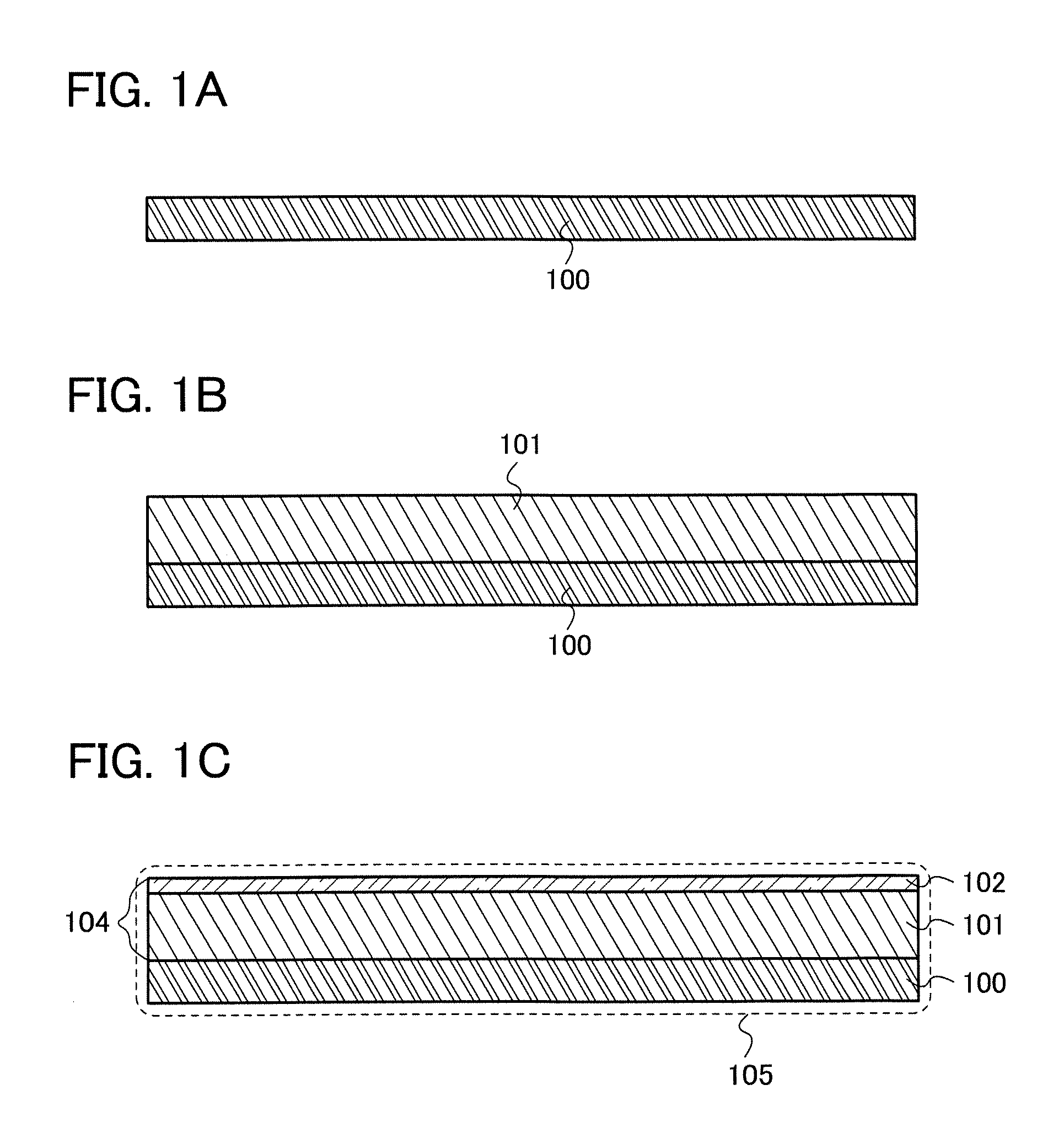
[0042]In this embodiment, a negative electrode-active material layer of a power storage device, a negative electrode that includes the negative electrode-active material layer that is provided over a current collector, and a manufacturing method thereof will be described with reference to FIGS. 1A to 1C.

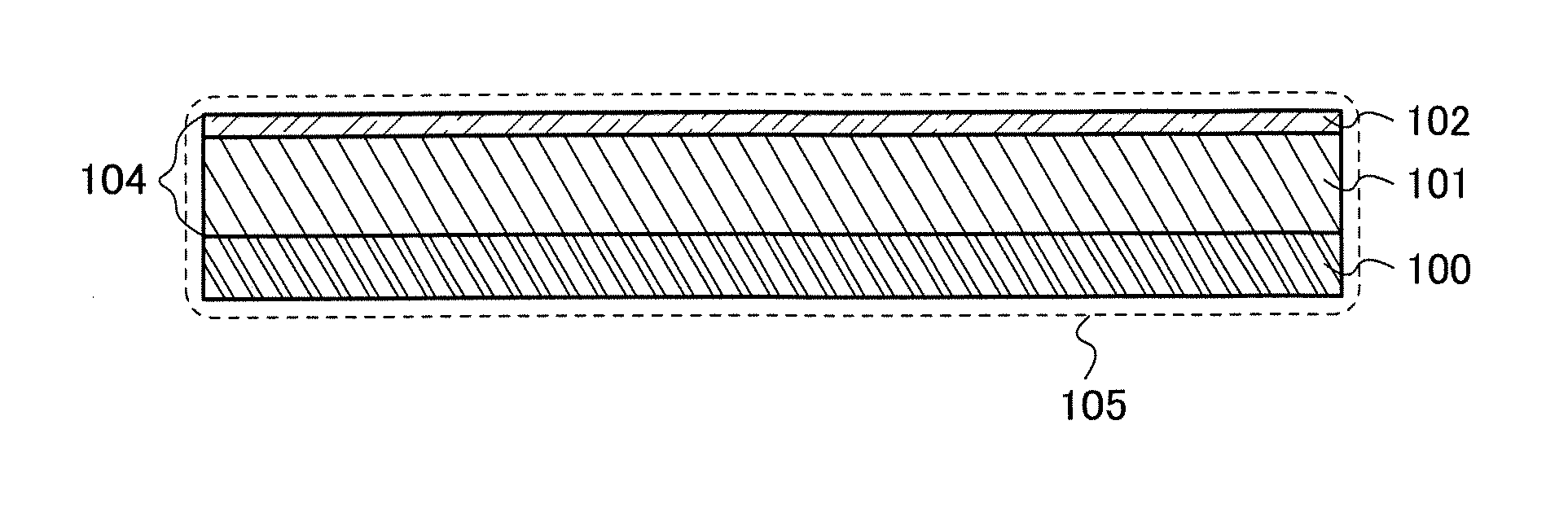
[0043]In this embodiment, a negative electrode-active material layer 104 will be described, which includes a first negative electrode layer 101 with a large capacitance per unit volume, and a second negative electrode layer 102 that is laminated over the first negative electrode layer 101 and is formed of a material with favorable adhesion to a solid electrolyte. Furthermore, in this embodiment, a negative electrode will be described in which the negative electrode-active material layer 104 is laminated over a current collector 100.

[0044]As a material for the first negative electrode layer 101, a material that can store and release ions functioning as carriers such as lithium ions an...

embodiment 2

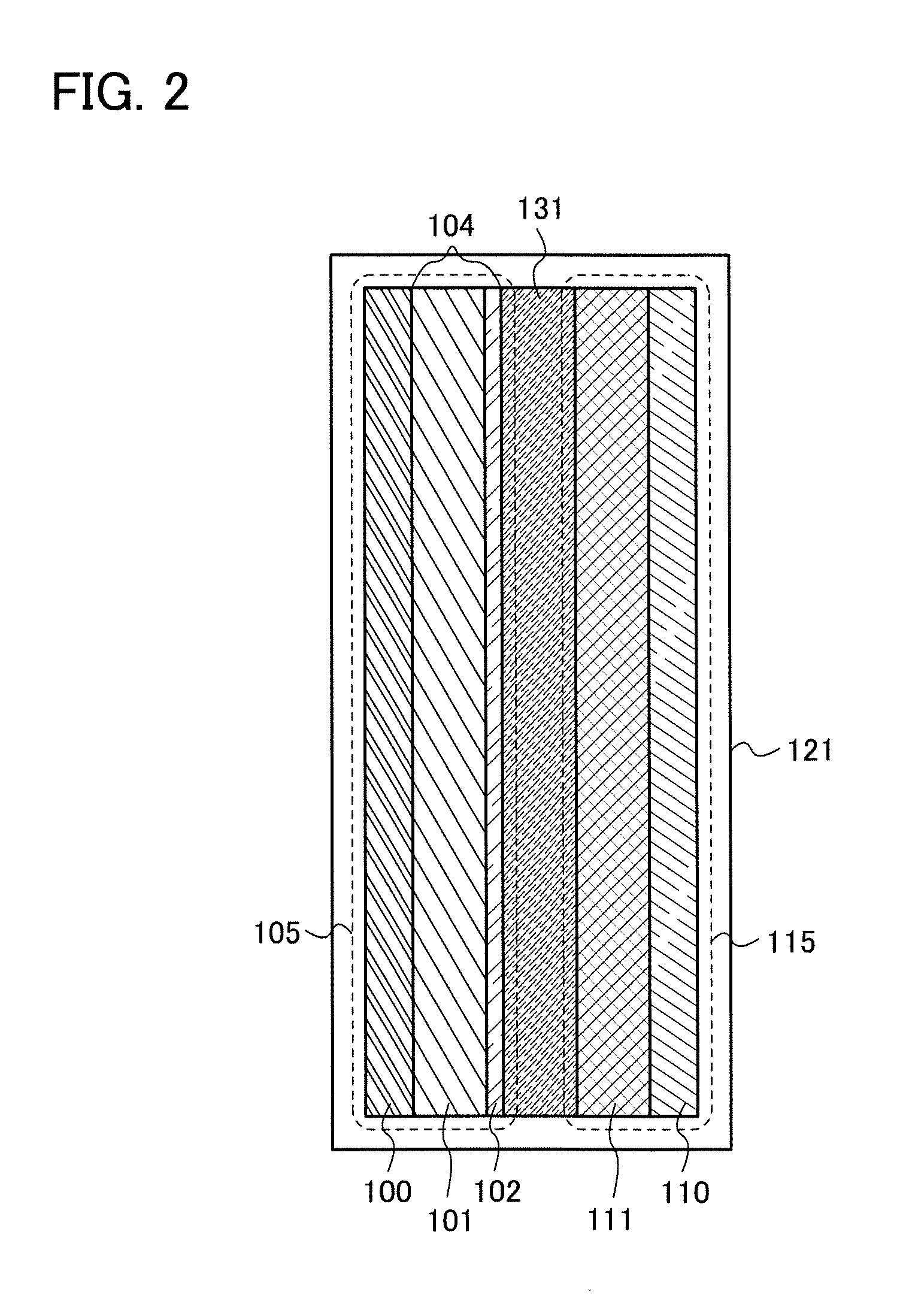
[0076]In this embodiment, as one example of a power storage device which is one mode of the present invention, a secondary battery and a manufacturing method thereof will be described with reference to FIG. 2, and FIGS. 3A and 3B.

[0077]A structure of a secondary battery of this embodiment is described with reference to FIG. 2. FIG. 2 is a pattern diagram showing an example of a structure of this embodiment.

[0078]The secondary battery shown in FIG. 2 includes the negative electrode 105 described in Embodiment 1, a positive electrode 115, and a solid electrolyte 131 interposed between the positive electrode 115 and the negative electrode 105.

[0079]As mentioned in Embodiment 1, the negative electrode 105 includes the current collector 100, and the negative electrode-active material layer 104 including the first negative electrode layer 101 and the second negative electrode layer 102 over the current collector 100. A material with which an interface with favorable adhesion to the solid ...

embodiment 3

[0102]As one example of a power storage device which is one mode of the present invention that is disclosed, a capacitor and a manufacturing method thereof will be described with reference to FIG. 4, and FIGS. 5A to 5D.

[0103]A structure of the capacitor of this embodiment is described with reference to FIG. 4. FIG. 4 is a pattern diagram showing one example of a structure of the capacitor of this embodiment.

[0104]The capacitor shown in FIG. 4 includes a negative electrode-active material layer 204 in which a first negative electrode layer 201 and a second negative electrode layer 202 are laminated. Also, the capacitor includes a negative electrode 205 in which the negative electrode-active material layer 204 is provided over the current collector 100. Furthermore, the capacitor includes the negative electrode 205, a positive electrode 215 that includes the current collector 110 and a positive electrode-active material layer 211, and the solid electrolyte 131 that is between the posi...


PUM

PropertyMeasurementUnit
thicknessaaaaaaaaaa
thicknessaaaaaaaaaa
volume changeaaaaaaaaaa

Abstract

An object is to improve characteristics of a power storage device. The present invention relates to an electricity storage device comprising a current collector and a negative electrode-active material layer formed over the current collector. The negative electrode-active material layer includes a negative electrode comprising a first negative electrode layer in contact with the current collector; a second negative electrode layer in contact with the first negative electrode layer, having a smaller capacitance than the first negative electrode layer and containing one material selected from a nitride of lithium and a transition metal represented by LiaMbNz (M is a transition metal, 0.1≦a≦2.8, 0.2≦b≦1 and 0.6≦z≦1.4), a silicon material, and lithium titanate; a positive electrode that is paired with the negative electrode; and a solid electrolyte interposed between the positive electrode and the negative electrode.

Description

BACKGROUND OF THE INVENTION[0001]1. Field of the Invention[0002]One mode of the present invention relates to an electricity storage device and a structure of a negative electrode of the electricity storage device.[0003]2. Description of the Related Art[0004]In recent years, with the advance of environmental technology, power generation devices (for example, solar power generation devices), which pose fewer burdens on the environment than conventional power generation methods, have been actively developed. Along with development of power generation devices, power storage devices have also been developed.[0005]As a power storage device, a secondary battery such as a lithium ion secondary battery (alternatively called a lithium ion storage battery or simply a lithium ion battery) can be given as example (see Patent Document 1). Lithium ion secondary batteries have high energy density and are widely popular because they are suited for miniaturization.[0006]Similarly, as a type of power ...

Claims


Application Information

Patent Timeline
Patent Type & Authority Applications(United States)
IPC IPC(8): H01M4/36H01M10/0562H01G11/06H01G11/22H01G11/30H01G11/56H01M4/13H01M4/131H01M4/134H01M4/136H01M4/38H01M4/485H01M4/58H01M10/052H01M10/0565
CPCH01M4/131H01M4/133H01M4/134H01M4/136H01M4/366H01M4/38Y02E60/122H01M4/587H01M10/0525H01M10/054H01M10/0565H01M2300/0085H01M4/58H01M4/386Y02E60/10H01M4/02H01M4/362H01M4/405
Inventor MORIWAKA, TAMAETAKAHASHI, TATSUYA
Owner SEMICON ENERGY LAB CO LTD
Why Eureka
Try Eureka