
High Pressure Apparatus and Method for Nitride Crystal Growth

Active Publication Date: 2011-07-28
SLT TECH
View PDF99 Cites 77 Cited by
  • Summary
  • Abstract
  • Description
  • Claims
  • Application Information

AI Technical Summary

Benefits of technology

[0016]The present invention enables a cost-effective high pressure apparatus for growth of crystals such as GaN, AlN, InN, InGaN, and AlInGaN. In a specific embodiment, the present method and apparatus operates with components that are relatively simple and cost effective to manufacture, such as ceramic and steel tubes. A specific embodiment also takes advantage of the one or more cracks provided in the ceramic member, which insulates the heater. Depending upon the embodiment, the present apparatus and method can be manufactured using conventional materials and / or methods according to one of ordinary skill in the art. The present apparatus and method enable cost-effective crystal growth and materials processing under extreme pressure and temperature conditions.

Problems solved by technology

Although somewhat effective for conventional crystal growth, drawbacks exist with conventional processing vessels.
As an example, processing capabilities for conventional steel hot-wall pressure vessels (e.g., autoclaves) are typically limited to a maximum temperature of about 400 Degrees Celsius and a maximum pressure of 0.2 GigaPascals (GPa).
Therefore, these conventional hot-wall pressure vessels are often inadequate for some processes, such as the growth of gallium nitride crystals in supercritical ammonia that often require pressures and temperatures that extend significantly above this range in order to achieve growth rates above about 2-4 microns per hour.
In addition, nickel-based superalloys are very expensive and are difficult to machine, limiting the maximum practical size and greatly increasing the cost compared to traditional steel pressure vessels.
Cemented tungsten carbide, however, is used as the die material, which is relatively expensive and is difficult to manufacture in large dimensions.
In addition, the use of a hydraulic press to contain the apparatus increases the cost and further limits the maximum volume.
Finally, the use of a pressure transmission medium surrounding the capsule used to contain the supercritical fluid reduces the volume available within the hot zone for processing material.
However, gas pressure vessels are generally not available in large sizes for pressure ratings substantially above 2000, 3000, or 5000 bar.
However, this apparatus requires non-standard heaters, and adventitious gaps within the apparatus may give rise to undesirable deformation of the capsule.
However, this apparatus similarly requires non-standard heaters, and adventitious gaps within the apparatus may give rise to undesirable deformation of the capsule.

Method used


Image

  • High Pressure Apparatus and Method for Nitride Crystal Growth
  • High Pressure Apparatus and Method for Nitride Crystal Growth
  • High Pressure Apparatus and Method for Nitride Crystal Growth

Examples


Embodiment Construction

[0023]The invention provides a high pressure apparatus for processing materials which may be vertically, horizontally or obliquely oriented. The apparatus may be rocked so as to facilitate convection of the supercritical fluid within the capsule.

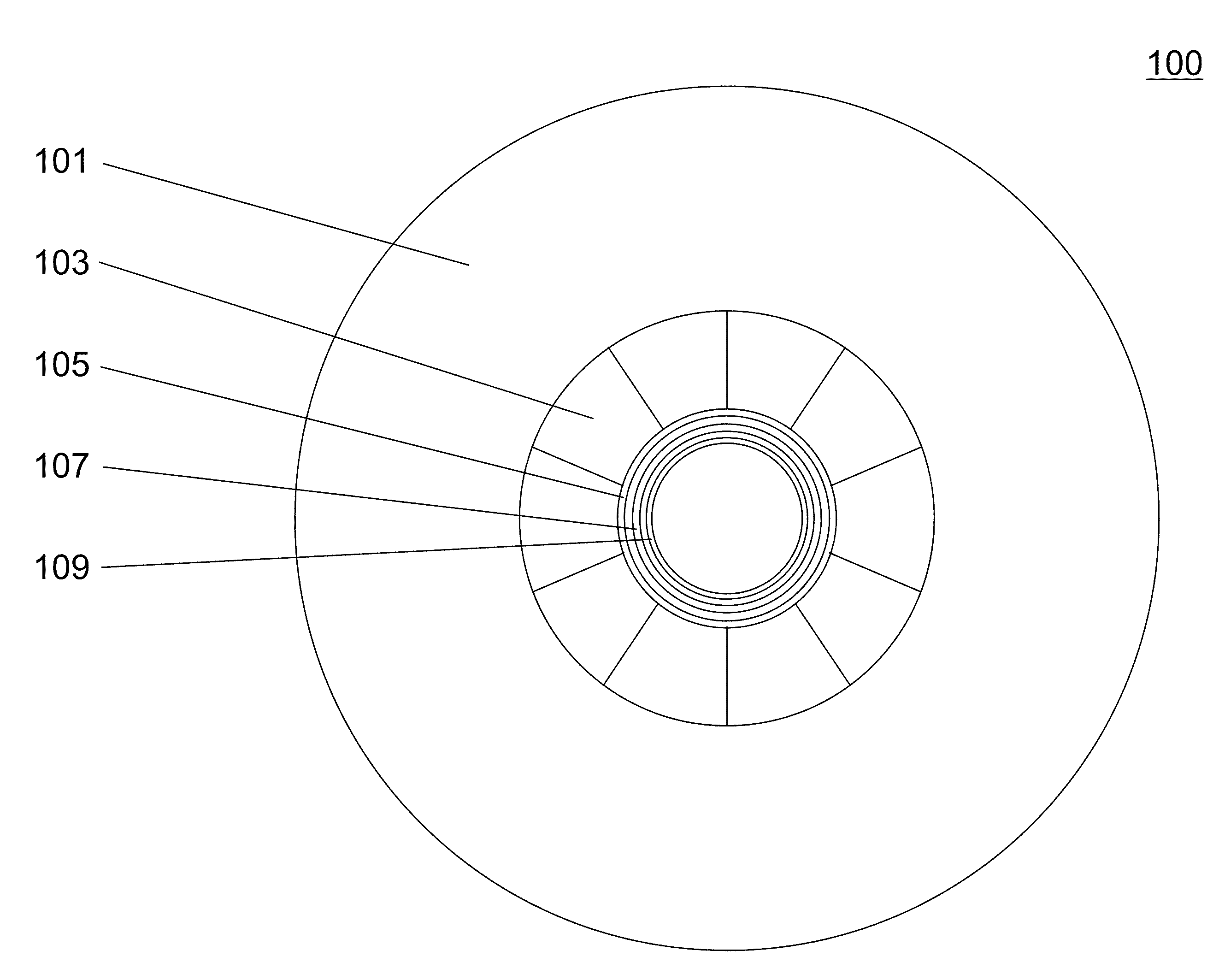
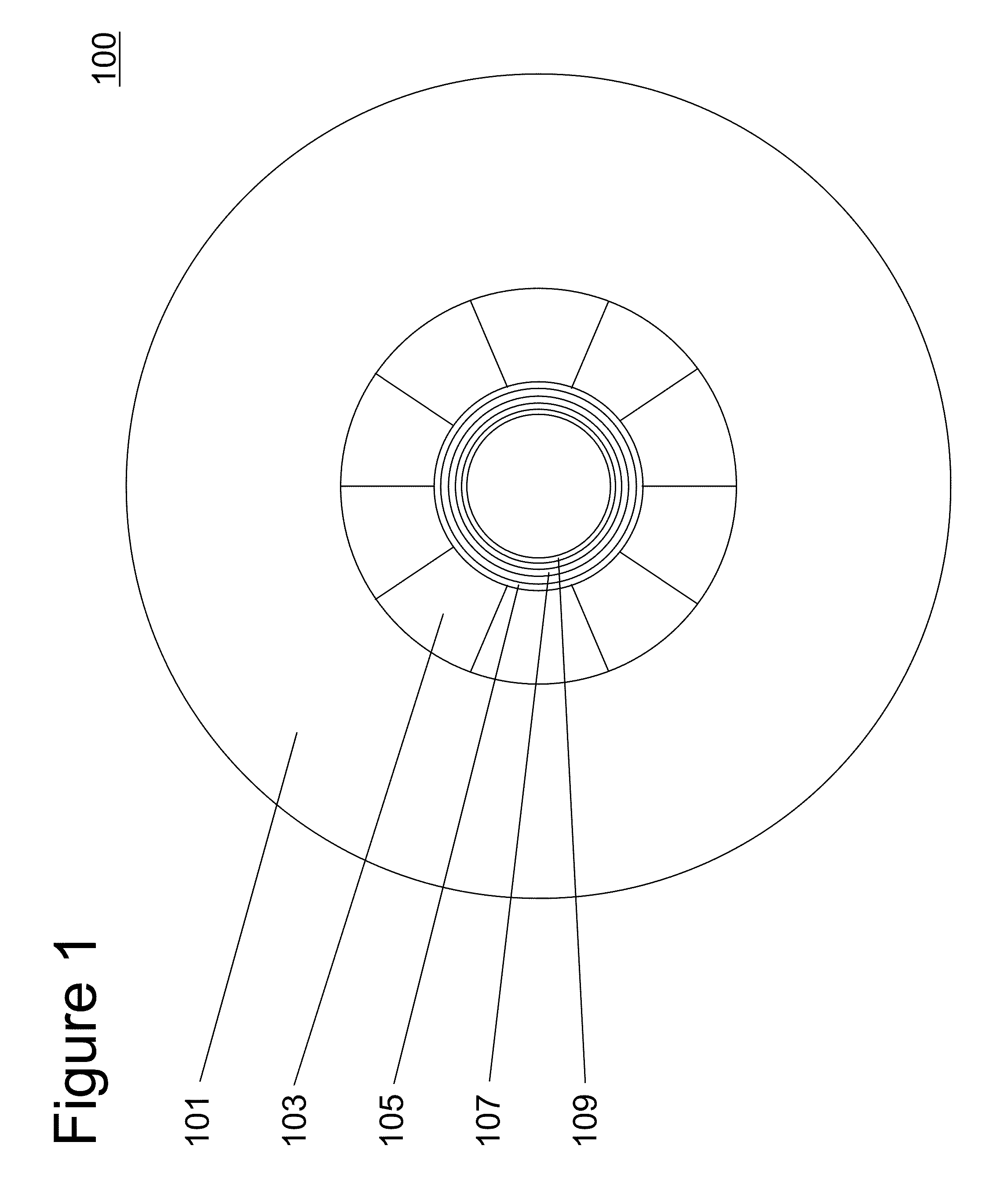
[0024]A cross-sectional view of a high-pressure apparatus 100 is shown schematically in FIG. 1. A capsule or liner 109 is placed within a heater 107, which in turn is placed within a sleeve 105, a plurality of radial segments 103, and a high strength enclosure 101. In some embodiments capsule 109 is sealed prior to placement in the high-pressure apparatus, as described in U.S. Pat. No. 7,125,453 or U.S. Patent Application No. 2009 / 0301388A1, each of which is incorporated by reference herein. In other embodiments, a liner 109 is used that is unsealed until being placed in high-pressure apparatus 100. The capsule or liner preferably includes copper, copper-based alloy, gold, silver, palladium, platinum, iridium, ruthenium, rhodium, osmium, tit...


PUM


Abstract

An improved high pressure apparatus and methods for processing supercritical fluids is described. The apparatus includes a capsule, a heater, and at least one ceramic ring contained by a metal sleeve. The apparatus is capable of accessing pressures and temperatures of 0.2-2 GPa and 400-1200° C.

Description

CROSS-REFERENCE TO RELATED APPLICATION[0001]The present application is a continuation-in-part application claiming priority to U.S. patent application Ser. No. 12 / 133,364, filed Jun. 5, 2008, commonly owned and hereby incorporated by reference for all purposes.BACKGROUND OF THE INVENTION[0002]The present invention relates generally to techniques for processing materials in supercritical fluids. More specifically, embodiments of the invention include techniques for controlling parameters associated with a material processing capsule disposed within a high-pressure apparatus enclosure. The invention can be applied to growing crystals of GaN, AlN, InN, InGaN, AlGaN, and AlInGaN, and others for manufacture of bulk or patterned substrates. Such bulk or patterned substrates can be used for a variety of applications including optoelectronic devices, lasers, light emitting diodes, solar cells, photoelectrochemical water splitting and hydrogen generation, photodetectors, integrated circuits,...

Claims


Application Information

Patent Timeline
IPC IPC(8): H01L21/20C30B7/02C30B7/08
CPCB01J3/008B01J3/042B01J3/065B01J2203/0665B01J2203/067Y10T117/1004C30B7/10C30B29/403C30B29/406Y10T117/1024B01J2203/068Y02P20/54
Inventor D'EVELYN, MARK P.
Owner SLT TECH
Learn More