High Resolution Electrohydrodynamic Jet Printing for Manufacturing Systems

a technology of electrohydrodynamic jet printing and manufacturing system, which is applied in the direction of printing, etc., can solve the problems that traditional ink jet printing methods are inherently limited with respect to applications requiring high resolution, and achieve the effect of high placement accuracy

Active Publication Date: 2011-08-04
THE BOARD OF TRUSTEES OF THE UNIV OF ILLINOIS
View PDF12 Cites 209 Cited by
  • Summary
  • Abstract
  • Description
  • Claims
  • Application Information

AI Technical Summary

Benefits of technology

[0010]The devices and methods disclosed herein recognize that by maintaining a smaller nozzle size, the electric field can be better confined to printing placement and access smaller droplet sizes. Accordingly, in an aspect of the invention, the ejection orifices from which printing fluid is ejected are of a smaller dimension than the dimensions in conventional inkjet printing. In an aspect the orifice may be substantially circular, and have a diameter that is less than 30 μm, less than 20 μm, less than 10 μm, less than 5 μm, or less than less than 1 μm. Any of these ranges are optionally constrained by a lower limit that is functionally achievable, such as a minimum dimension that does not result in excessive clogging, for example, a lower limit that is greater than 100 nm, 300 nm, or 500 nm. Other orifice cross-section shapes may be used as disclosed herein, with characteristic dimensions equivalent to the diameter ranges described. Not only do these small nozzle diameters provide the capability of accessing ejected and printed smaller droplet diameters, but they also provide for electric field confinement that provides improved placement accuracy compared to conventional inkjet printing. The combination of a small orifice dimension and related highly-confined electric field provides high-resolution printing.
[0032]The devices and methods disclosed herein provide the capacity of printing features, including nanofeatures or microfeatures, by e-jet printing with an extremely high placement accuracy, such as in the sub-micron range, without the need for surface pre-treatment processing.

Problems solved by technology

Traditional ink jet printing methods are inherently limited with respect to applications requiring high resolution.
The printing resolution is high-resolution, e.g., a resolution that is not possible with conventional inkjet printing known in the art without substantial pre-processing steps.

Method used


Image

  • High Resolution Electrohydrodynamic Jet Printing for Manufacturing Systems
  • High Resolution Electrohydrodynamic Jet Printing for Manufacturing Systems
  • High Resolution Electrohydrodynamic Jet Printing for Manufacturing Systems

Examples


example 1

High Resolution E-jet System and Process Overview

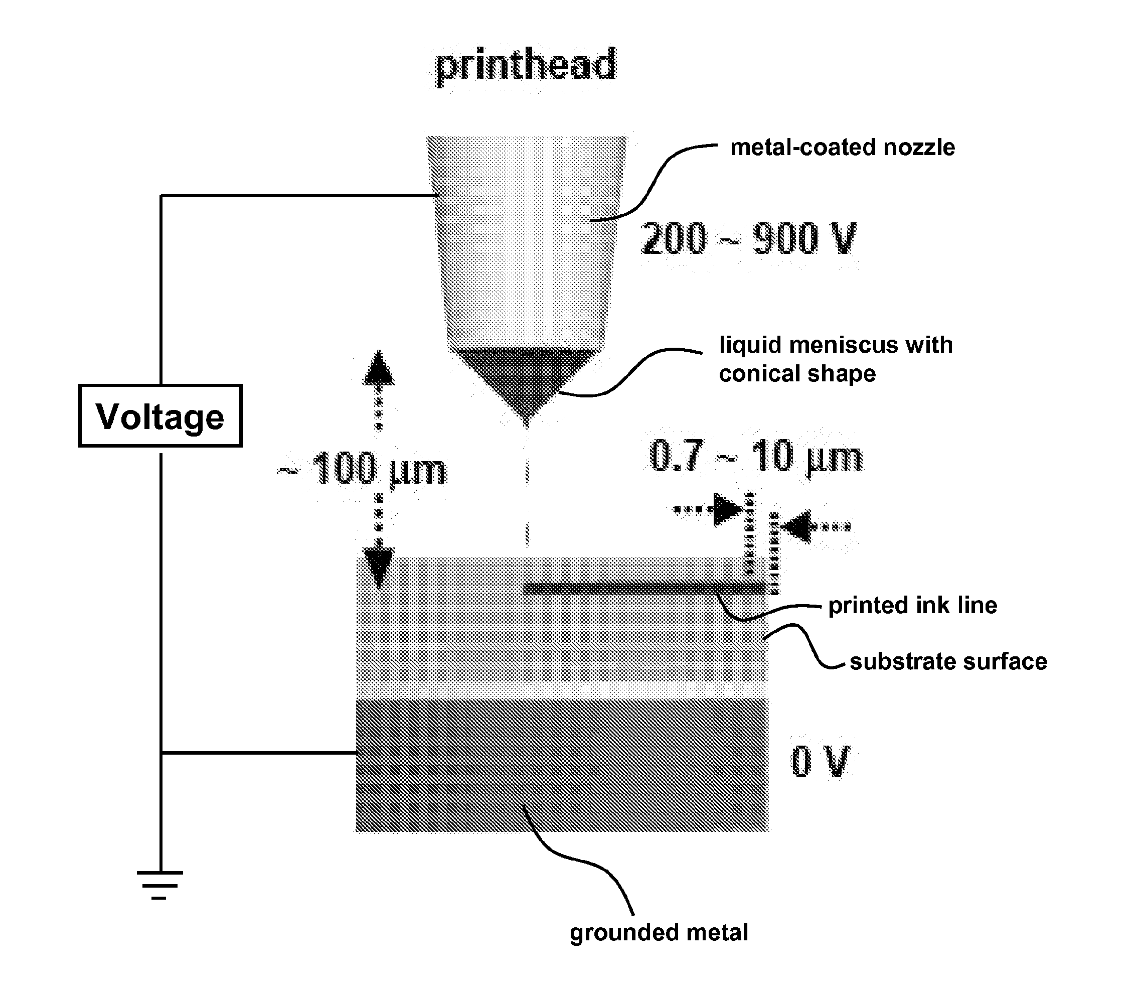
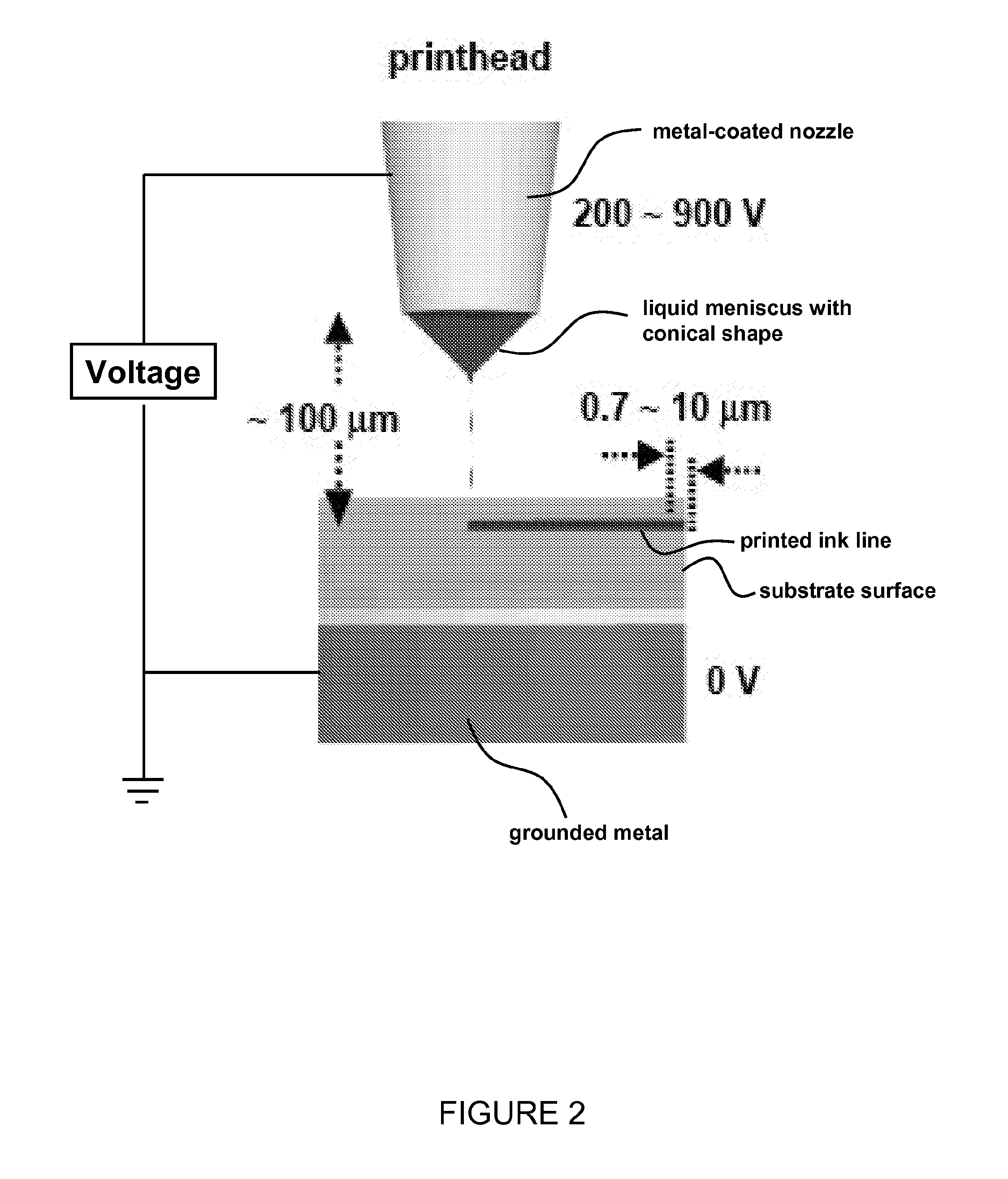
[0094]Efforts to adapt and extend graphic arts printing techniques for demanding device applications in electronics, biotechnology and microelectromechancial systems have grown rapidly in recent years. This example describes the use of electrohydrodynamically-induced fluid flows through fine microcapillary nozzles for jet printing of patterns and functional devices with sub-micron resolution. Key aspects of the physics of this approach, which has some features in common with related but comparatively low-resolution techniques for graphic arts, are revealed through direct high speed imaging of the droplet formation processes. Printing of complex patterns of inks, ranging from insulating and conducting polymers, to solution suspensions of silicon nanoparticles and rods, to single walled carbon nanotubes, using integrated, computer-controlled printer systems illustrates some of the capabilities. High resolution, printed metal interconnec...

example 2

Printed Electronics

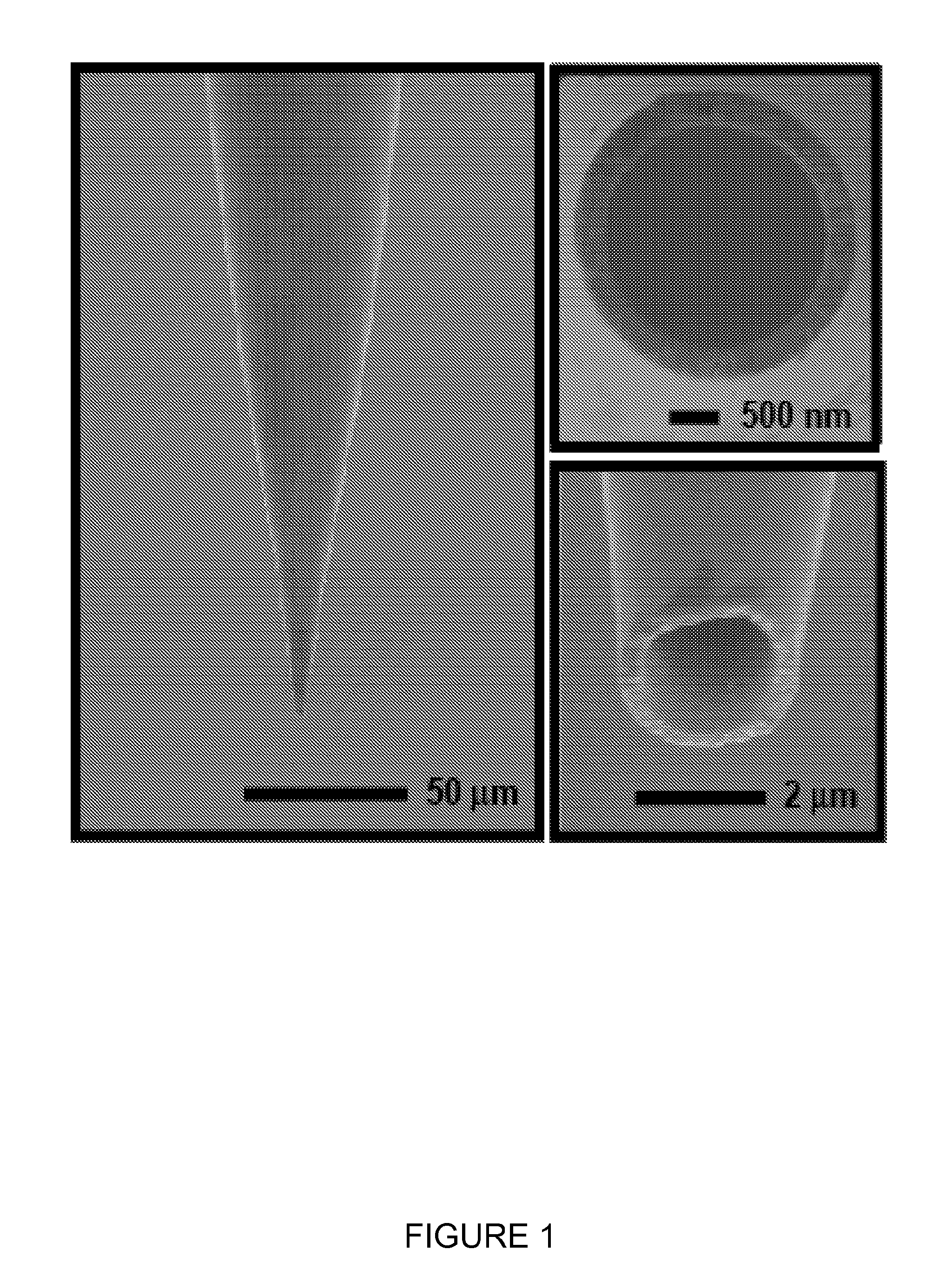
[0147]Printed electronics represents an important application area that can take advantage of both the extremely high-resolution capabilities of e-jet as well as its compatibility with a range of functional inks. To demonstrate the suitability of e-jet for fabricating key device elements in printed electronics, we pattern complex electrode geometries for ring oscillators, source / drain electrodes for transistors, and manufacture working transistors. In these examples, a photocurable polyurethane precursor provides a printable resist layer for patterning metal electrodes by chemical etching. The printhead in this case uses a 1 μm ID nozzle; the printing speed is 100 μm s−1. The substrate consists of a SiO2(300 nm) / Si coated uniformly with Au (130 nm) and Cr (2 nm). FIG. 9a shows a pattern of printed polyurethane after curing by exposure to ultraviolet light (˜1 J cm−2). The resolution is 2±0.4 μm, as defined by the minimum line widths. Much larger features, shown he...

example 3

Scanned Nozzles

[0152]Printing of active and passive materials using scanned small-diameter nozzles represents an attractive method for organic electronics and optoelectronics, partly because the high level of sophistication of similar systems used in graphic arts. Because of the additive nature of the process, materials utilization can be high. The materials can be deposited either in the vapor or liquid phase using respectively vapor jet printing or inkjet methods. While organic vapor jet printing techniques have been introduced only very recently, inkjet printing techniques are well-established and already have worldwide applications. In 2004, a 40-inch full-color OLED display prototype was fabricated using inkjet printing of light emitting polymers.317 The following summarize recent developments in inkjet printing techniques applied to the fabrication of organic optoelectronic devices.

[0153]Nozzles can be used to print liquids. Beginning shortly after the commercial introduction ...


PUM


Abstract

Provided are high-resolution electrohydrodynamic inkjet (e-jet) printing systems and related methods for printing functional materials on a substrate surface. In an embodiment, a nozzle with an ejection orifice that dispenses a printing fluid faces a surface that is to be printed. The nozzle is electrically connected to a voltage source that applies an electric charge to the fluid in the nozzle to controllably deposit the printing fluid on the surface. In an aspect, a nozzle that dispenses printing fluid has a small ejection orifice, such as an orifice with an area less than 700 μm2 and is capable of printing nanofeatures or microfeatures. In an embodiment the nozzle is an integrated-electrode nozzle system that is directly connected to an electrode and a counter-electrode. The systems and methods provide printing resolutions that can encompass the sub-micron range.

Description

CROSS-REFERENCE TO RELATED APPLICATIONS[0001]This application claims benefit of U.S. Provisional Patent Application 60 / 950,679 filed Jul. 19, 2007.BACKGROUND OF THE INVENTION[0002]Inkjet printing technology is well known for use in printing images onto paper. Inkjet technology is also used in the fabrication of printed circuits by directly printing circuit components onto circuit substrates. Inkjet printing-based approaches for high resolution manufacturing have inherent advantages and are of interest for a number of reasons. First, functional inks are deposited only where needed, and different functional inks are readily printed to a single substrate. Second, inkjet printing provides the ability to directly pattern wide classes of materials, ranging from fragile organics or biological materials that are incompatible with other established patterning methods such as photolithography. Third, inkjet printing is extremely flexible and versatile in that structure design changes are easi...

Claims


Application Information

Patent Timeline
Patent Type & Authority Applications(United States)
IPC IPC(8): B41J2/06
CPCB41J2/06B41J2/16B41J2/1628B41J2/1629B41J2/1645B41J2/1632B41J2/1639B41J2/1642B41J2/1631B41J2/09B41J2/14314B41J2/162
Inventor ROGERS, JOHN A.PARK, JANG-UNGFERREIRA, PLACID M.MUKHOPADHYAY, DEEPKISHORE
Owner THE BOARD OF TRUSTEES OF THE UNIV OF ILLINOIS
Why Eureka
Try Eureka