Magnet wire

a magnetic wire and wire technology, applied in the field of magnetic wires, can solve the problems of reducing the conductivity of the iron core, lowering iron loss, and induced copper loss, and achieve the effect of reducing the resistance of high-frequency alternating current (ac) and saving energy

Inactive Publication Date: 2011-08-18
ELECTRIC WIRE & CABLE
View PDF8 Cites 28 Cited by
  • Summary
  • Abstract
  • Description
  • Claims
  • Application Information

AI Technical Summary

Benefits of technology

[0011]The primary objective of the present invention is to provide a magnetic wire that compensates induced interference curr...

Problems solved by technology

In addition, silicon efficiently reduce conductivity of the iron core when it is added into the iron core and lowering iron loss due to the eddy current.
Besides resistance loss of the copper wire, copper loss is also induced by skin effect and proximity effect in a high-frequency operation.
Therefore, copper loss becomes serious and affects transformation between energies.
Alternatively, lengthening a diameter of the enameled wire can also lower the resistance loss.
However, the foregoing policies cost a lot.
However, twisted enameled wires consist of multiple conductors that each is covered with an insulating cover, so the conventional method is complicated and expensive and easily makes conductors broken or results in poor soldering ability at ends of each conductor.
However, this patent doe...

Method used

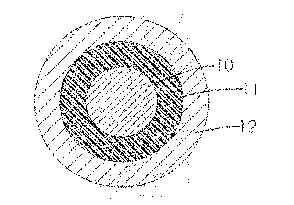
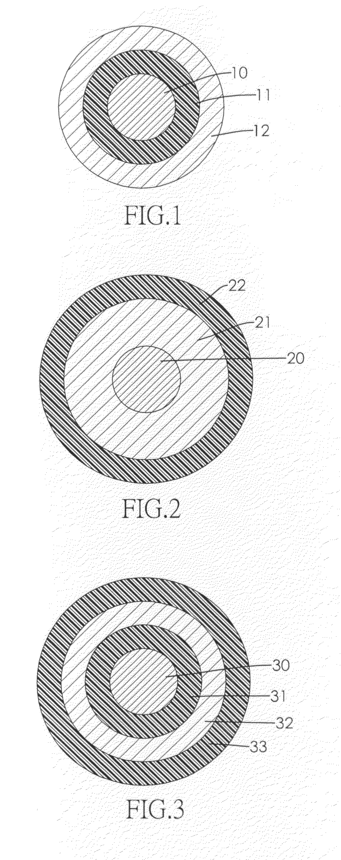
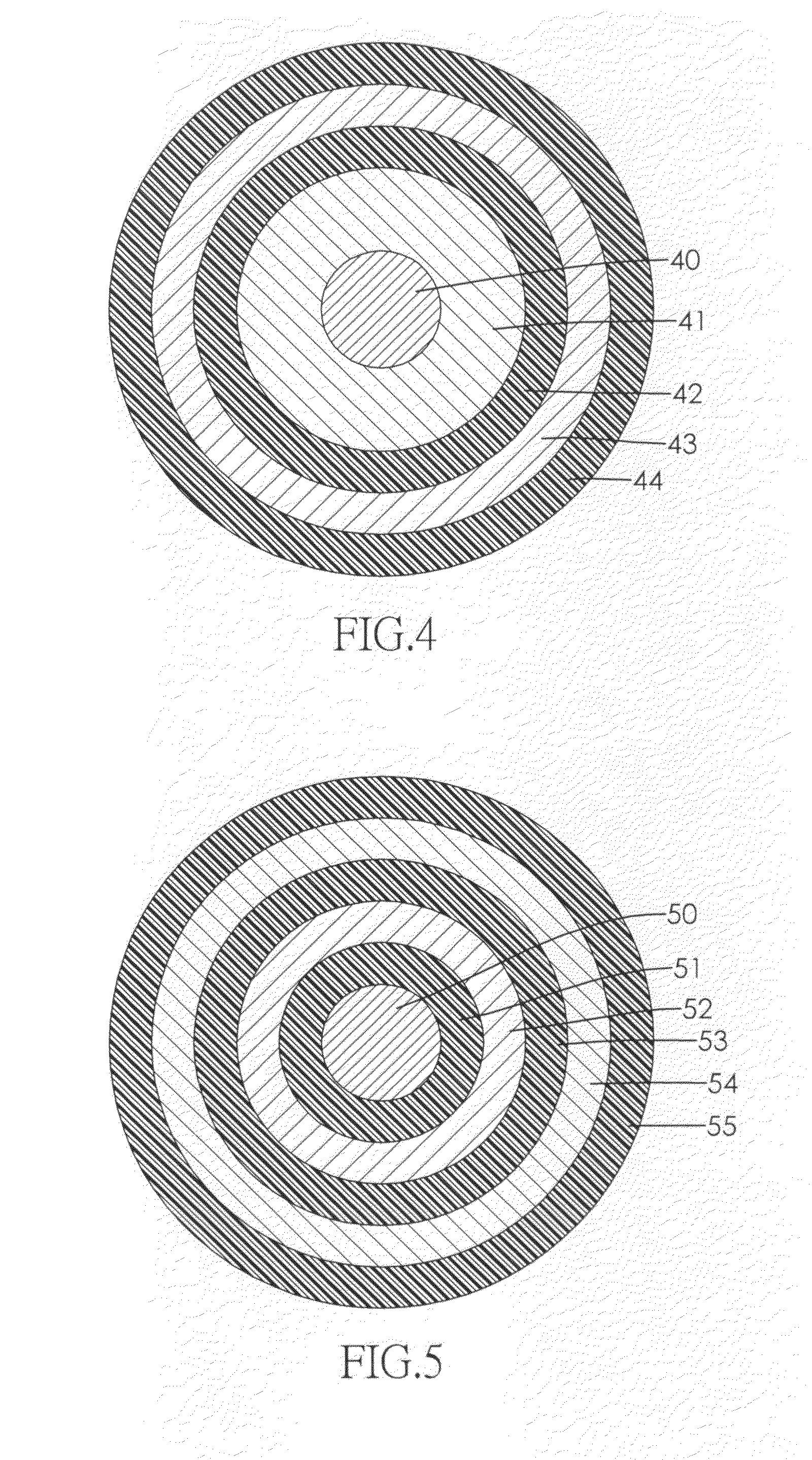

Image

  • Magnet wire
  • Magnet wire
  • Magnet wire

Examples


example 1

[0044]20 part of γ-Fe2O3 was added into 100 part of polyurethane coating and they were blended for 24 hours with ball mill to form a magnetic material. The magnetic material was coated around a copper wire (0.31 mm) with a die for five times with a line speed of 60˜70 meter / min to form a magnetic coating layer; then polyurethane coating was coated around the magnetic coating layer with a die for five times with a line speed of 60˜70 meter / min to form an insulating coating layer; and the magnetic coating layer and the insulating coating layer were cured at 440˜500° C. to form a magnet wire with a layer of magnetic coating layer and a layer of insulating coating layer.

example 2

[0045]20 part of γ-Fe2O3 was surface treated by 5 part of oleic acid, then was added into 100 part of polyurethane coating and they were blended for 24 hours with ball mill to form a magnetic material. A magnet wire with a layer of magnetic coating layer and a layer of insulating coating layer was produced using the same steps as described in example 1.

example 3

[0046]15 part of γ-Fe2O3 was added into 100 part of polyurethane coating and they were blended for 24 hours with ball mill to form a magnetic material. A magnet wire with a layer of magnetic coating layer and a layer of insulating coating layer was produced using the same steps as described in example 1.

[0047]Results:

[0048]The magnet wires of comparative example and examples of the present invention were tested according to NEMA MW-75C and presented characteristics shown in Table 1.

TABLE 1Test and results for comparative example 1 and examples of the present inventionTestComp. Ex. 1Ex. 1Ex. 2Ex. 3AppearancegoodgoodgoodgoodAdherencegoodgoodgoodgoodFlexibilitygoodgoodgoodgoodElongation(%)30.630.932.834.0Single-direction scrape resistance1480141911871196Heat shockgoodgoodgoodgoodThermoplastic flow (° C.)251246238222SolderabilitygoodgoodgoodgoodDielectric breakdown voltage (KV)9.428.438.608.97Conductor resistance(Ω / km)232.9228.4227.5228.5200 kHz AC resistance(Ω)*11.651.531.601.56Lower...


PUM

PropertyMeasurementUnit
Temperatureaaaaaaaaaa
Fractionaaaaaaaaaa
Lengthaaaaaaaaaa

Abstract

A magnet wire has a conductor and a coating layer. The coated layer is coated around the conductor and has at least one magnetic coating layer; and at least one insulating coating layer. The magnetic coating layer has non-conductive magnetic material. The insulating coating layer and the magnetic coating layer are formed alternately. The alternative structure of the magnetic coating layer and the insulating coating layer prevent precipitation of magnetic material and efficiently offsets the interference between conductors after electricity is supplied, which inhibits occurrence of eddy current and lowers alternative current (AC) resistance.

Description

BACKGROUND OF THE INVENTION[0001]1. Field of Invention The present invention relates to a magnetic wire, and more particularly to a magnetic wire that compensates induced interference currents to overcome proximity effect and skin effect, which lowers high-frequency alternating current (AC) resistance and saves energy.[0002]2. Description of the Related Art[0003]Coil, usually used in a transformer or other electronic device, controls inductor and transform voltage with electromagnetic induction. However, energy is eliminated during every transformation between electricity and magnetism. Especially in a high frequency operation, energy elimination is more apparent, which is resulted from “eddy current loss” due to “iron loss” in the iron core and “copper loss” of enameled wire. Eddy current is occurred when a conductor is exposed to a changing magnetic field due to alternating current (AC), so an induced current, which flows inversely in the conductor, is generated to oppose the chan...

Claims


Application Information

Patent Timeline
IPC IPC(8): H05K9/00H01R43/00
CPCH01B3/302H01B3/303H01B3/308H01B3/421Y10T29/49117H01F1/10H01F1/344H01F41/32H05K9/0098H01B7/0208
Inventor FANG, TSANG-TSECHUNG, HAN-YANGHUNG, CHI-FENGLU, TING-ICHOU, KUANG-CHIANGCHUANG, PA-KUELCHEN, CHUN-HUNGCHIU, JUNG-KUNSHEN, SHANG-HUI
Owner ELECTRIC WIRE & CABLE
Why Eureka
Try Eureka