Method and System for Sootblower Flow Analyzer

a flow analyzer and flow filter technology, applied in the direction of machines/engines, flushing, lighting and heating apparatus, etc., can solve the problems of increasing the risk of tube erosion, reducing the efficiency of boilers, and reducing the efficiency of sootblowing processes, so as to improve the efficiency of sootblowing process and the boiler availability rating, reduce the number of leakage of tubes, and improve the effect of the net plant heat ra

Inactive Publication Date: 2011-08-25
NRG ENERGY
View PDF23 Cites 11 Cited by
  • Summary
  • Abstract
  • Description
  • Claims
  • Application Information

AI Technical Summary

Benefits of technology

[0014]The invention focuses on the flow of the cleaning medium and thus improves the efficiency of the sootblowing process and the boiler availability rating due to reduced tube leaks. The invention improves the net plant heat rate numbers. Rapid identification of specific sootblower flow rates outside of specific set points can prevent significant damage to the boiler.

Problems solved by technology

When soot accumulates on the heat transfer tubes, the heat transfer efficiency of the tubes decreases and thus the boiler efficiency is reduced.
But in many cases, doing so makes the cleaning system part of the problem rather than the solution, by increasing the risk of tube erosion caused by the sootblowing operation.
Injection of a cleaning medium into the boiler can prematurely damage heat transfer surfaces in the boiler, especially if they are over cleaned.
Boiler surface and water wall damage resulting from sootblowing is particularly costly because repair requires boiler shutdown, cessation of power production and immediate attention that cannot wait for scheduled plant outages.
Conversely, undercleaning can have the effect of not removing enough of the soot buildup and thus decreasing the efficiency of the boiler operation as measured by net heat rate.
Problems with the use of sensors for determining soot buildup include 1) the difficulty in installing and maintaining the sensors within the boiler, 2) the costs of installing the sensors and 3) the requirement to shut the boiler down for installation or repair.
Butler fails to provide a monitoring system or method for controlling the mass flow rate of the cleaning medium and ensure operation within high and low setpoints for optimization of cleaning medium usage and sootblowing operation effectiveness.
During the sootblowing operation it is challenging to understand what is occurring inside of a boiler and specifically what is occurring relative to a specific sootblower and section of the boiler and whether damage is occurring to the heat exchanger tubes.
Sootblowers can get stuck inside a boiler flowing steam which can lead to heat transfer tube leaks or higher than normal tube erosion.
Sootblowers can also become damaged allowing for excessive cleaning medium flow.
A boiler may be required to be taken out of service due to heat transfer tube damage from the sootblowing.
During the sootblowing process, variations of the cleaning medium flow rates outside of a certain range can cause problems and reduce the effectiveness of the operation.
A cleaning medium directed at a heat transfer tube at too high of a flow rate can quickly cause damage to a section of heat transfer tube requiring the boiler to be shut down for repair.
A cleaning medium directed at a heat transfer tube at too low of a flow rate can lose its effectiveness in removing soot from the tubes.
In either case, the cleaning medium is not being optimized and adjustments need to be made to the sootblowing process.

Method used


Image

  • Method and System for Sootblower Flow Analyzer
  • Method and System for Sootblower Flow Analyzer
  • Method and System for Sootblower Flow Analyzer

Examples


Embodiment Construction

[0021]For a fuller understanding of the nature and objects of the present invention, reference should be made to the following detailed description taken in connection with the accompanying drawings, wherein:

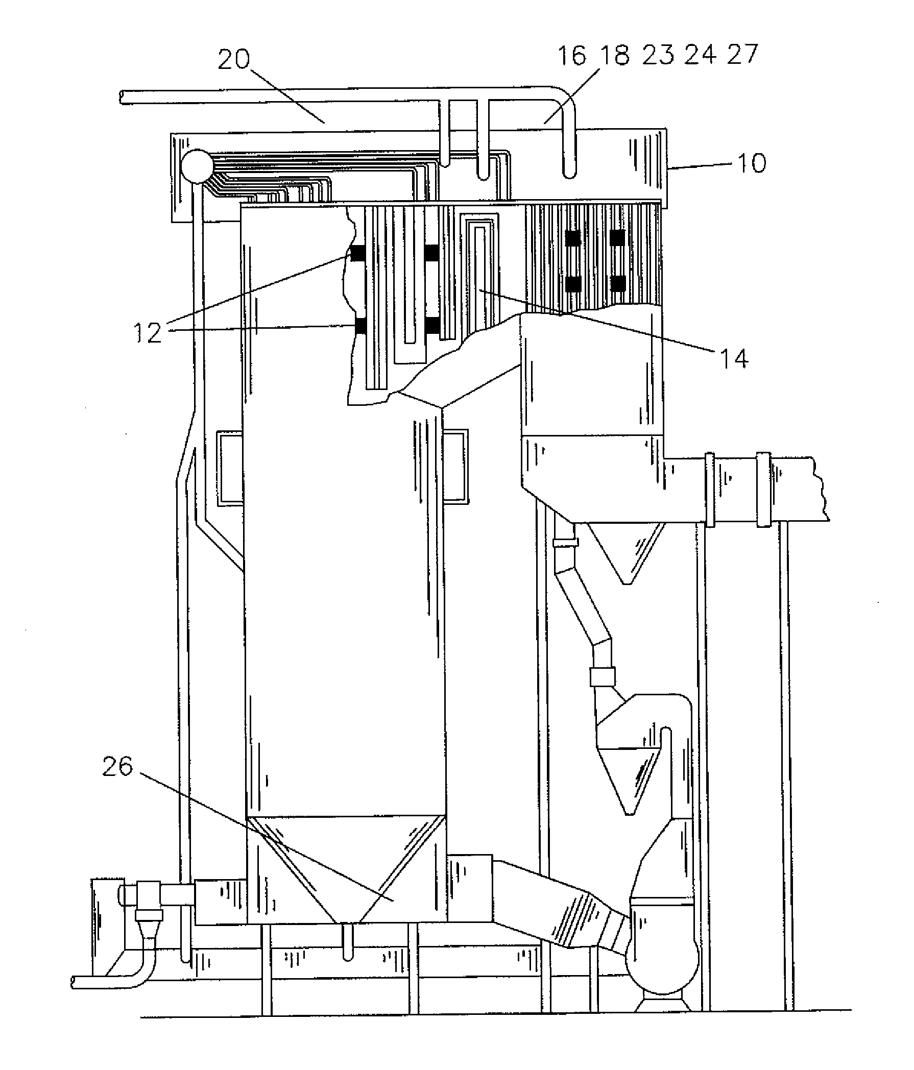
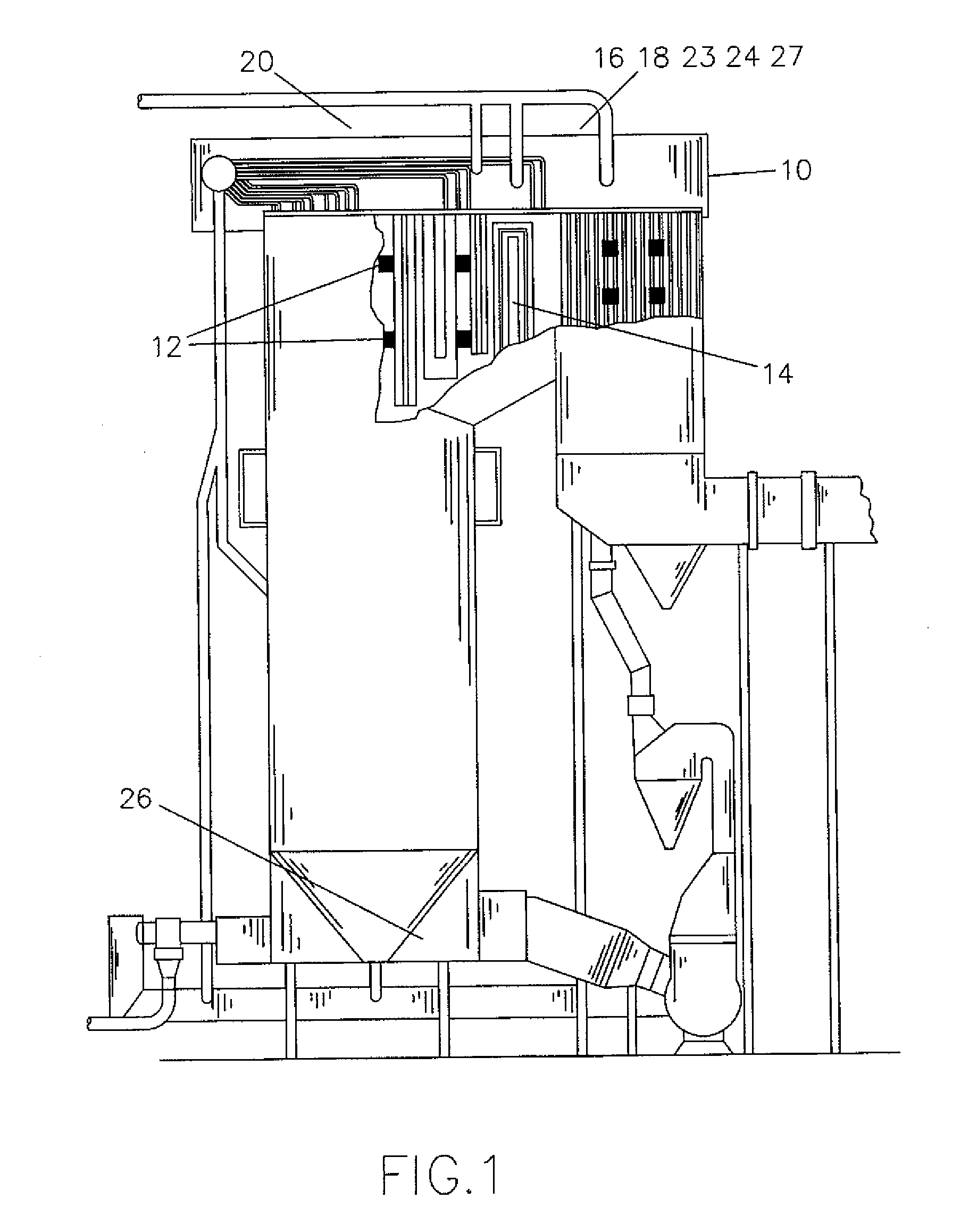
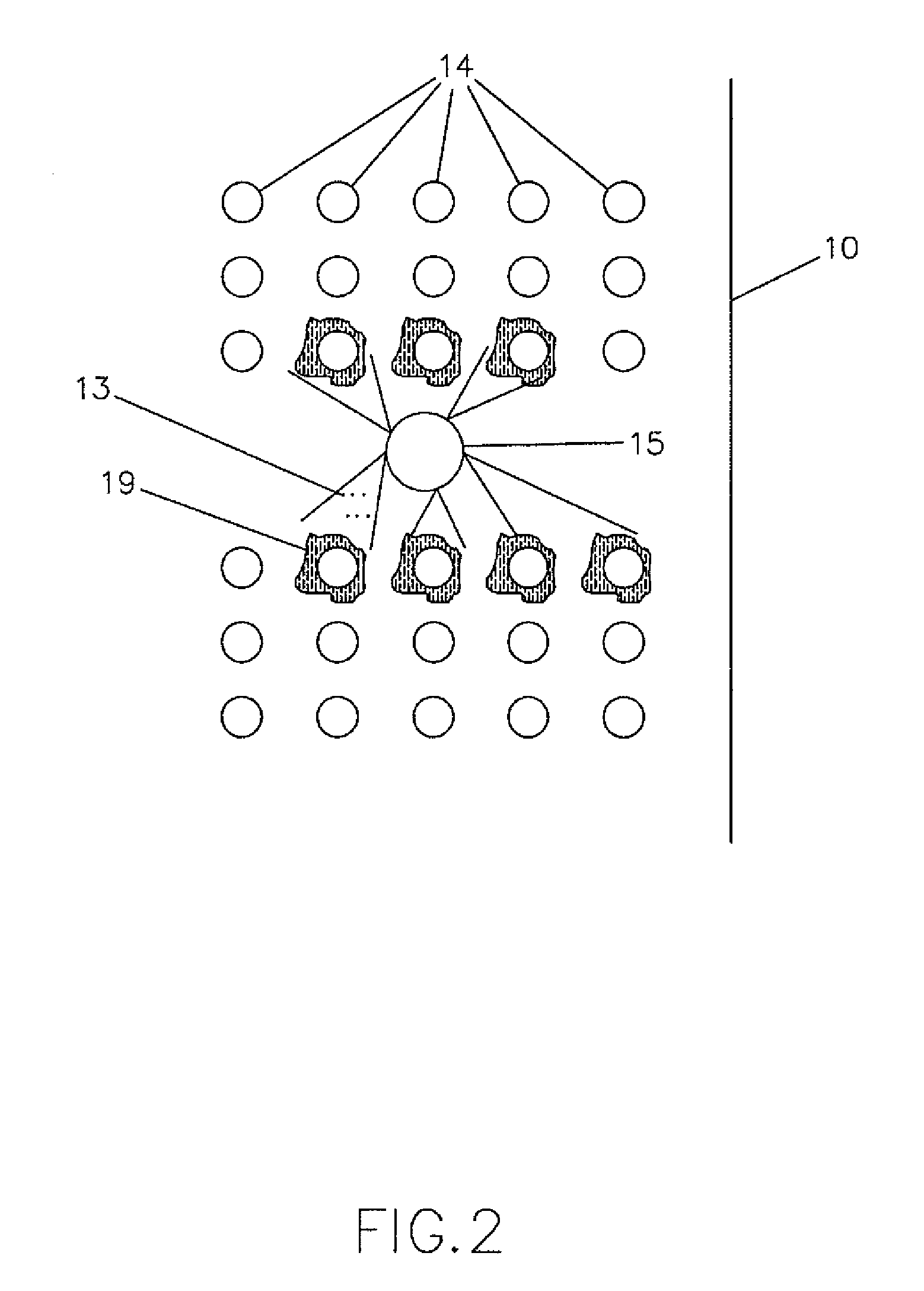
[0022]FIG. 1 is drawing of a power plant boiler 10 with portions broken away to show the heat exchanger tubes 14 within the power plant boiler 10 which are to be cleaned by sootblowers 12. Attached to the cleaning medium line 20 is a mass flow measurement device 16 and a temperature measuring device 18 installed upstream. The mass flow measurement device 16 includes flow transmitter 23. The temperature measuring device 18 includes a temperature transmitter 24. The steam pressure measuring device 27 of the cleaning medium is measured upstream of the cleaning medium line 20. The physical drain valves 26 are shown located at the system low point for automatic removal of the cleaning medium, for example for steam then water is removed. For leak testing, the physical drain valves 26 ...


PUM


Abstract

The present invention relates to a method and a system for optimizing steam or other cleaning medium used during soot removal in a boiler in which energy is generated by fuel combustion, with accompanying production of soot, and heat energy is transferred from the product gases to a heated medium via heat exchanger tubes on which the soot collects, by; monitoring the mass flow rate of the cleaning medium, determining which set of sootblowers are in operation, calculating appropriate high flow alarm set point and low flow set point for each particular sootblower, notifying an operator whether the sootblowers are operating within the setpoints so that appropriate action can be taken to the set of sootblowers. In addition, the invention performs leak detection by monitoring for a system bottled up situation and notifies the operator when a steam leak is detected.

Description

FIELD OF THE INVENTION[0001]This invention relates generally to increasing the efficiency of boiler operation and specifically to improving sootblower operations by optimizing cleaning medium usage during boiler cleaning. This invention will also detect system leaks or clean medium flows above or below system specifications, this will reduce the potential for boiler tube erosion.DESCRIPTION OF THE RELATED ART[0002]The combustion of coal and other fossil fuels during the production of steam or electricity produces combustion deposits, i.e., ash or soot, that builds up on the surfaces in the boiler. When soot accumulates on the heat transfer tubes, the heat transfer efficiency of the tubes decreases and thus the boiler efficiency is reduced. These deposits are removed periodically by directing a cleaning medium, e.g., air, steam, water or mixtures thereof, against the surfaces upon which the deposits have accumulated at a high pressure or high thermal gradient with cleaning devices kn...

Claims


Application Information

Patent Timeline
Patent Type & Authority Applications(United States)
IPC IPC(8): F22B37/56F28G1/16F28G15/00
CPCF22B37/56F28G15/00F28G1/166F28G15/003
Inventor HYMEL, MICHAEL CLARK
Owner NRG ENERGY
Why Eureka
Try Eureka