Reluctance And Lorentz-Force-Operated Linear Drive

a linear drive, lorentz-force-operated technology, applied in the direction of electric controllers, instruments, ignition automatic control, etc., can solve the problems of linear drive sluggishness, rigid system and limited optical quality, and inability to adjust the focal length of the lens, so as to reduce static and sliding friction, the effect of reducing static and sliding friction and reducing sliding friction in the interior of the motor

Active Publication Date: 2011-09-01
KARL STORZ GMBH & CO KG
View PDF10 Cites 15 Cited by
  • Summary
  • Abstract
  • Description
  • Claims
  • Application Information

AI Technical Summary

Benefits of technology

[0008]The embodiments are based on the object of providing a linear motor having such small dimensions that this can be inserted in endoscopes. Furthermore, the linear motor should have a defined zero point position and a reproducible deflection as a function of the control signal. In addition, the linear motor should exhibit large driving forces with small mass and thereby render possible a rapid, continuous and exact positioning of the optical system in the largest possible range. At the same time, the beam path through the optical system must not be blocked during displacement of the components. The power loss of the linear motor should be low so that little heat is produced in the tip of an endoscope. The drive should be composed of as few as possible and as geometrically simple as possible individual components for simple manufacture and assembly.
[0015]The linear motor enables an exact adjustment of the position of the armature relative to the stator between two end positions. In the linear motor a unique position of the armature in relation to the stator corresponds to each coil current. Consequently, the armature can be continuously displaced in the travel range by means of an adjustment of the coil current. As a result of this unique assignment between the coil current and the armature position, the path measurements necessary according to the prior art to determine the position of the armature can be dispensed with. The individual components have a simple geometry (rings, sleeves) and therefore can easily be manufactured and assembled.
[0017]The linear motor can easily be miniaturized up to a size of a few millimeters external diameter. In a motor having an external diameter of a few millimeters, the travel distance between the two end positions of the armature is typically about 1 to 3 mm.
[0018]In a further advantageous embodiment there is a sliding layer between the stator and the armature. The sliding layer can compensate for unevennesses on the side of the stator facing the armature.
[0021]It is particularly favorable if the coil is supplied with a direct current with a superposed alternating current of small amplitude and having a frequency up to a maximum of 1 kHz. The static and sliding friction can be reduced by this means.

Problems solved by technology

As a result of the rod lenses, the system is rigid and limited in optical quality.
An adjustment of the focal length of the lens is not possible.
However, as a result of the large mass of the permanent magnet, the linear drive is sluggish.
The complex structure of the drive can be readily implemented in video cameras having lens diameters in the centimeter range but is not scalable to the size required for endoscope applications in the millimeter range.
An expensive control circuit is required to produce the moving field.
A disadvantage here is the dependence of the stroke and the adjusting forces on the soft-magnetic stator pole pieces, with the result that a high precision is required in the manufacture and assembly of these parts.

Method used


Image

  • Reluctance And Lorentz-Force-Operated Linear Drive
  • Reluctance And Lorentz-Force-Operated Linear Drive
  • Reluctance And Lorentz-Force-Operated Linear Drive

Examples


Embodiment Construction

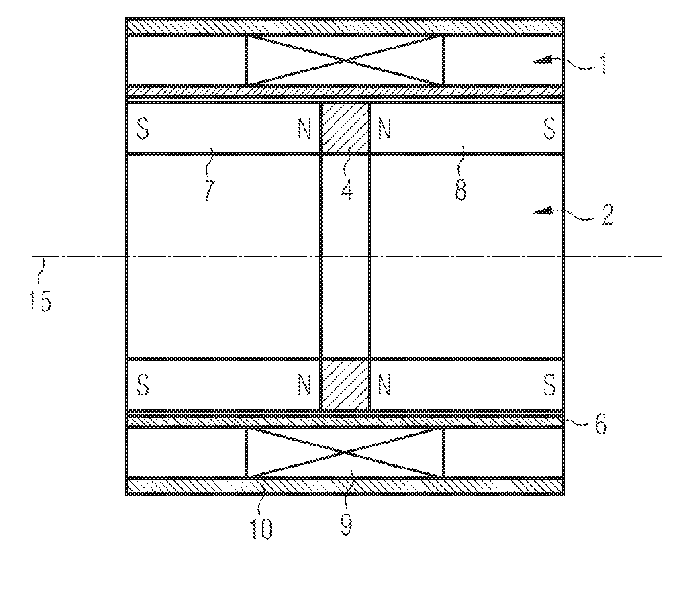
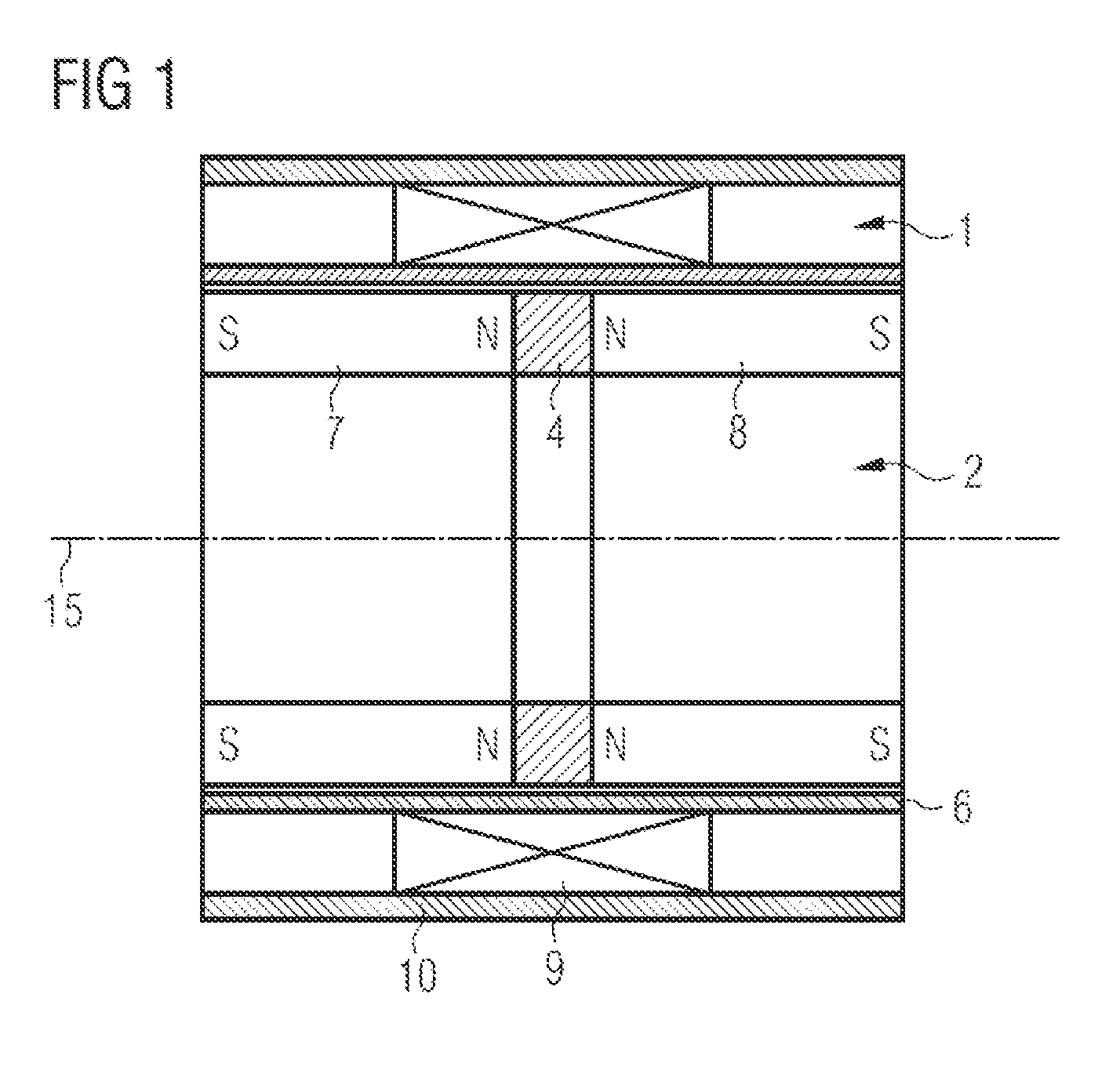
[0033]FIG. 1 shows schematically an exemplary embodiment of a linear motor in cylindrical design in a sectional view. The stator 1 includes a magnetic guiding member 10 in the form of a tube, a coil 9 being disposed in the bore whereof. The magnetic guiding member preferably consists of soft magnetic material, like a ferromagnetic material. Said coil is enclosed by the magnetic guiding member over its entire length, i.e. it does not project beyond the magnetic guiding member. A sliding sleeve 6 terminates the stator 9 here towards the inside and provides a sliding layer for the armature. The sliding sleeve must consist of a non-ferromagnetic material. The armature 2 is surrounded, at least partially, by the coil and has a first permanent magnet and a second permanent magnet. Here the armature 2 includes two oppositely magnetized permanent magnets 7, 8 and an interposed pole piece 4, which enables a defined emergence of the magnetic fields of the permanent magnets through the coil in...


PUM


Abstract

A linear motor for optical systems, for example, endoscopes, is described. The motor has a stator with a magnetic guiding member and a coil. The armature of the motor includes two permanent magnets which are of opposite polarity. A pole piece made of soft-magnetic material is provided between the permanent magnets. By applying current to the coil, the armature can be displaced from a rest position in the longitudinal direction.

Description

CROSS-REFERENCE TO RELATED APPLICATIONS[0001]This application claims priority to pending German Application No. 10 2010 000 583.5 filed on Feb. 26, 2010.FIELD OF THE INVENTION[0002]The invention relates to a linear motor in particular for optical systems. Such optical systems are used, for example, in endoscopes. In modern video endoscopes a camera chip and an appurtenant lens system are integrated in the endoscope tip. A miniaturized motor is required to adjust the focal length or the focus of the lens system.BACKGROUND OF THE INVENTION[0003]Classical endoscopes such as can be used, for example, for minimally invasive surgery, guide the image by means of rod lenses from the intracorporeal objective to the extracorporeal eyepiece. As a result of the rod lenses, the system is rigid and limited in optical quality. Modern video endoscopes use a camera chip in the endoscope tip. Such an endoscope is disclosed in U.S. Pat. No. 7,365,768 B1. This has a rigidly disposed lens in front of th...

Claims


Application Information

Patent Timeline
IPC IPC(8): G05B11/01H02K41/035
CPCH02K41/031H02K1/2713H02K7/106A61B1/00158H02K7/14A61B1/0016H02K7/08A61B1/00188
Inventor VOGEL, WALTER
Owner KARL STORZ GMBH & CO KG
Why Eureka
Try Eureka