
Substrate with surface-collection-layer and catalyst-carrying substrate with surface-collection-layer

a catalyst-carrying substrate and surface collection technology, which is applied in the direction of catalyst carriers, physical/chemical process catalysts, separation processes, etc., can solve the problems of engine output dropping to an unacceptable level, affecting the performance of the engine, and reducing the pressure loss of the exhaust system, etc., to achieve high particulate matter collection efficiency, low pressure loss, and sufficient partition wall strength

Active Publication Date: 2011-09-01
NGK INSULATORS LTD
View PDF10 Cites 33 Cited by
  • Summary
  • Abstract
  • Description
  • Claims
  • Application Information

AI Technical Summary

Benefits of technology

[0007]Therefore, development of a filter (substrate with a surface-collection-layer) for a gasoline direct injection engine has been desired. Specifically, development of a substrate with a surface-collection-layer that has a sufficient partition wall strength, a low pressure loss, and a high particulate matter collection efficiency, and may be used for a gasoline direct injection engine, has been desired.
[0008]The present invention was conceived in view of the above problems. An object of the present invention is to provide a substrate with a surface-collection-layer and a catalyst-carrying substrate with a surface-collection-layer that have a sufficient partition wall strength, a low pressure loss, and a high particulate matter collection efficiency, and may be used for a gasoline direct injection engine.
[0010]The substrate with a surface-collection-layer of the present invention has advantages that a sufficient partition wall strength, a low pressure loss, and a high particulate matter collection efficiency, and may be used for a gasoline direct injection engine.
[0011]The catalyst-carrying substrate with a surface-collection-layer of the present invention has advantages that a sufficient partition wall strength, a low pressure loss, and a high particulate matter collection efficiency, and may be used for a gasoline direct injection engine.

Problems solved by technology

On the other hand, a gasoline direct injection engine has a problem in that particulate matter (e.g., soot) is produced due to combustion of gasoline, differing from an intake port fuel injection engine.
In this case, however, the following problems may occur.
(1) When installing the above filter in addition to a three-way catalyst converter or a NOx adsorption / reduction catalyst used for a conventional gasoline engine exhaust treatment, the pressure loss of the exhaust system increases, so that the engine output decreases to an unacceptable level.
However, there is a problem that the pressure loss of the wall-flow type filter increases when coating the wall-flow type filter with the three-way catalyst.
In this case, however, the particulate matter (e.g., soot) collection efficiency decreases.
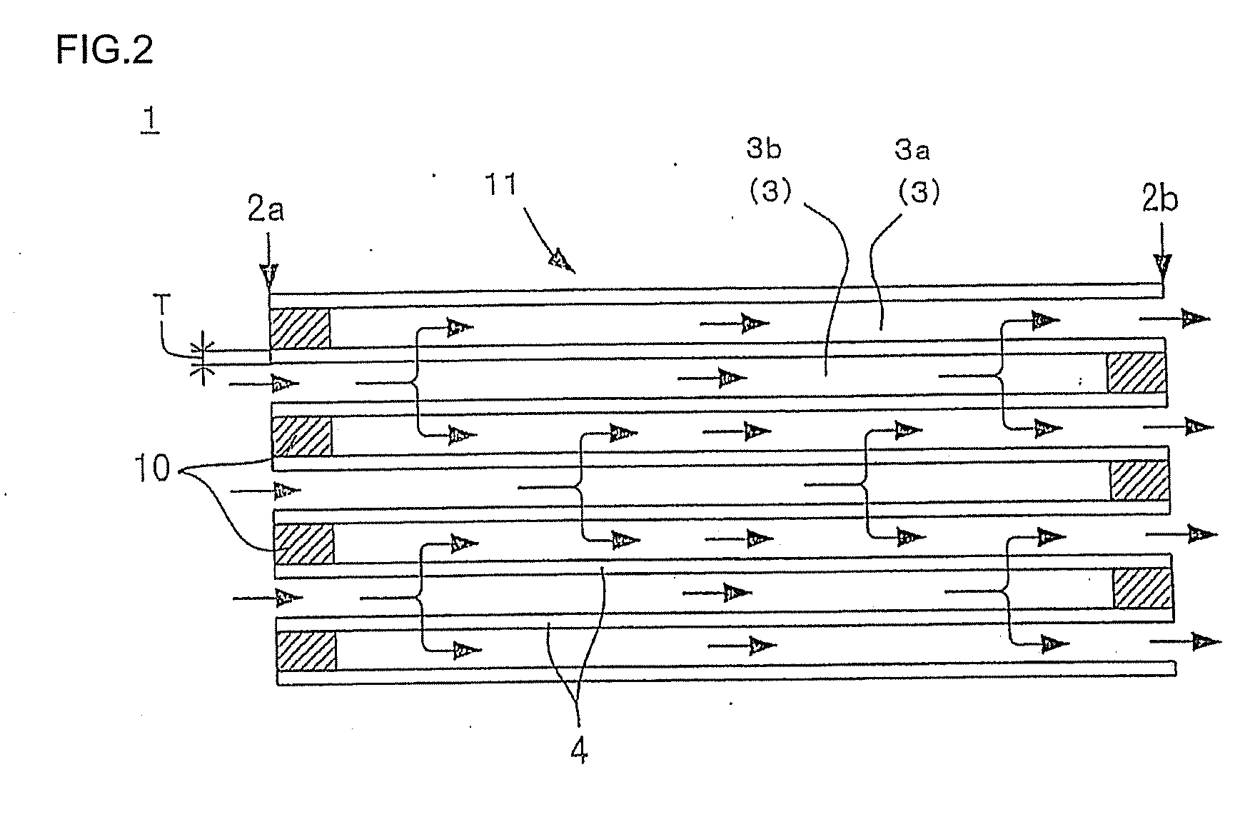
(4) When coating the wall-flow type filter with a three-way catalyst to implement a gas purification function, since the flow of gas that passes through the partition wall is concentrated in an area around the outlet (outlet-side open end face 2b), as shown in FIG. 7, there is a problem that the catalyst supported in an area around the outlet deteriorates to a large extent.

Method used


Image

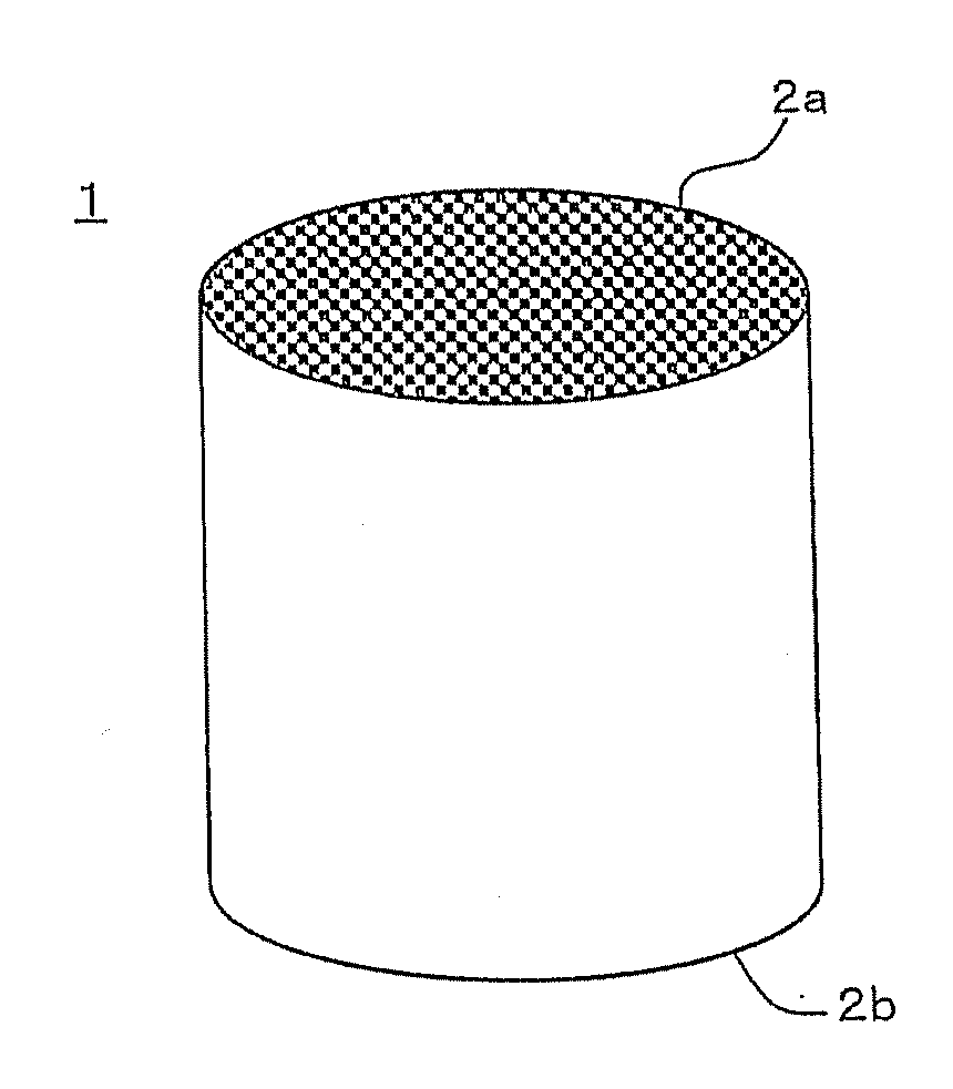
  • Substrate with surface-collection-layer and catalyst-carrying substrate  with surface-collection-layer
  • Substrate with surface-collection-layer and catalyst-carrying substrate  with surface-collection-layer
  • Substrate with surface-collection-layer and catalyst-carrying substrate  with surface-collection-layer

Examples


example 1

Preparation of Plugged Honeycomb Structure

[0084]Alumina, aluminum hydroxide, kaolin, talc, and silica were used as cordierite-forming raw materials. 13 parts by mass of a pore-forming material, 35 parts by mass of a dispersion medium, 6 parts by mass of an organic binder, and 0.5 parts by mass of a dispersant were added to 100 parts by mass of the cordierite-forming raw materials. The mixture was then kneaded to obtain a kneaded clay.

[0085]Water was used as the dispersion medium, coke having an average particle diameter of 10 μm was used as the pore-forming material, hydroxypropylmethyl cellulose was used as the organic binder, and ethylene glycol was used as the dispersant. The kneaded clay was extruded using a given die to obtain a cylindrical honeycomb formed body having a quadrangular cell shape.

[0086]The honeycomb formed body was then dried using a microwave dryer, completely dried using a hot-blast dryer, and cut at each end (adjusted to given dimensions) to obtain a dried hon...

example 23

[0090]First, a substrate with a surface-collection-layer was produced in the same manner as in Example 1, except for employing the conditions shown in Table 2. The resulting catalyst-carrying substrate with a surface-collection-layer was coated with a catalyst to obtain a catalyst-carrying substrate with a surface-collection-layer.

[0091]Specifically, a catalyst slurry containing platinum (Pt) (noble metal), activated alumina, and ceria (oxygen adsorption agent) was prepared. The mass ratio of platinum, activated alumina, and ceria was platinum:activated alumina:ceria=1:80:20. Then, a coating layer was formed on the inner surface and inside the pores of the partition wall of the substrate with a surface-collection-layer by a suction method using the above obtained catalyst slurry. The coating layer was formed by immersing the outlet-side end of the substrate with a surface-collection-layer in the catalyst slurry, and sucking the catalyst slurry through the inlet-side end (i.e., the c...


PUM

PropertyMeasurementUnit
Fractionaaaaaaaaaa
Fractionaaaaaaaaaa
Fractionaaaaaaaaaa

Abstract

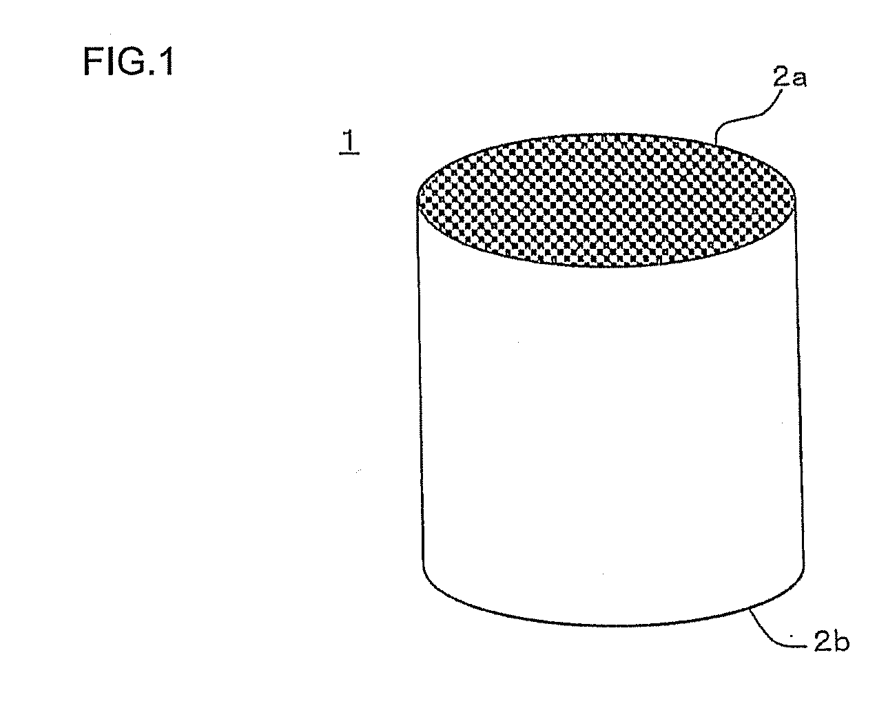
A substrate with a surface-collection-layer comprising a honeycomb substrate having a porous partition wall that defines and forms cells, and a plurality of plugging portions, a surface-collection-layer being formed on a surface of the partition wall that forms the remaining cells, the thickness of the surface-collection-layer on the outlet-side open end being larger than the thickness of the surface-collection-layer in a center area of the substrate, the partition wall having predetermined thickness, porosity and pore size, the surface-collection-layer having predetermined thickness, porosity, and average pore size, and the substrate having predetermined cell density.

Description

TECHNICAL FIELD[0001]The present invention relates to a substrate with a surface-collection-layer and a catalyst-carrying substrate with a surface-collection-layer. More particularly, the present invention relates to a substrate with a surface-collection-layer and a catalyst-carrying substrate with a surface-collection-layer that have a sufficient partition wall strength, a low pressure loss, and a high particulate matter collection efficiency, and may be used for a gasoline direct injection engine.BACKGROUND ART[0002]Exhaust gas discharged from an internal combustion engine (e.g., diesel engine) or a combustion apparatus (hereinafter may be appropriately referred to as “internal combustion engine or the like”) contains a large amount of particulate matter (hereinafter may be appropriately referred to as “particulate matter”, “particulate” or “PM”) that mainly contains soot (black smoke). If particulate matter is directly discharged to the atmosphere, environmental pollution occurs....

Claims


Application Information

Patent Timeline
IPC IPC(8): B01J35/04B01J32/00B01J35/10
CPCB01D46/2474B01D2279/30Y02T10/22F01N2510/0682Y02T10/20F01N3/0222F01N2560/06F01N2590/08F01N2590/10Y02T10/12B01D46/2484B01D46/2482B01D46/24492B01D46/2429B01D46/247B01D46/24491
Inventor GOTO, CHIKAYAMASHITA, MASATAKAMIYAIRI, YUKIO
Owner NGK INSULATORS LTD
Learn More